

Prototype Injection Mold Design Checklist: 8 Key Steps
Introduction
A prototype mold is built quickly, but it should not be designed casually. The purpose of prototype injection molding is to obtain reliable information about the part and process before production tooling. If the mold design ignores wall thickness, draft, gating, ejection or cooling, the resulting samples may create misleading conclusions. A structured injection mold design checklist helps engineers identify risk before steel is cut. HPDI’s prototype molding services are centered on this validation stage, where tool design and part design are reviewed together.
Key Prototype Injection Mold Design Review Items
| Design Item | Main Risk if Ignored | Prototype Review Goal |
|---|---|---|
| Draft | Sticking / drag marks | Clean release |
| Wall thickness | Sink / warpage / short shot | Stable filling and cooling |
| Undercuts | Tool complexity | Choose manual or automated action |
| Gate location | Weld lines / cosmetic marks | Balanced fill and acceptable appearance |
| Ejection / cooling | Deformation | Repeatable dimensions |
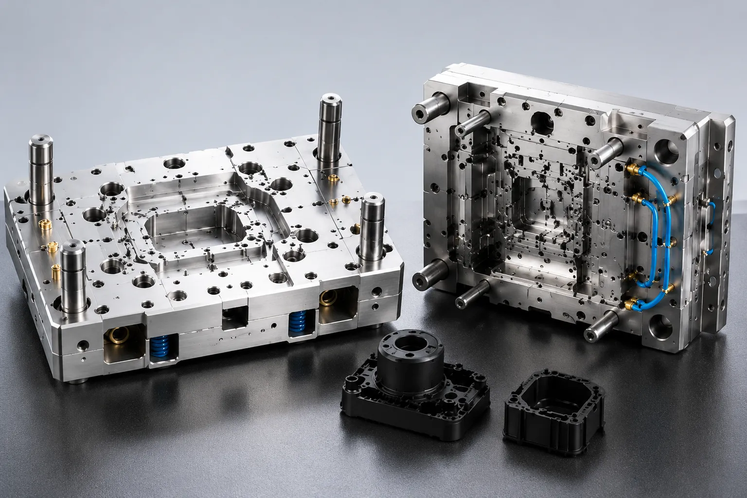
1. Confirm the Mold Opening Direction
Start by deciding how the part will separate from the mold. The opening direction determines which surfaces need draft, where the parting line will appear and which features become undercuts. Changing the pull direction later can affect almost every other element of the tool. For cosmetic parts, also consider where the parting line can be hidden or controlled.
2. Review Wall Thickness and Transitions
Uniform wall thickness supports more consistent filling and cooling. Sudden thick sections can cause sink, voids and differential shrinkage, while very thin sections may be difficult to fill. Where more stiffness is needed, ribs or gussets are often better than simply making a wall much thicker. Gradual transitions reduce stress concentration and help the resin flow more predictably.
3. Add Practical Draft
Draft helps the part release from the cavity and core. Deep ribs, textured surfaces and tall bosses generally need more consideration than short polished walls. Insufficient draft can cause drag marks, whitening or excessive ejection force. A prototype tool is the right stage to confirm whether the selected draft still satisfies both appearance and assembly requirements.
4. Evaluate Ribs, Bosses and Snap-Fits
Ribs should support stiffness without creating excessive local thickness. Bosses need enough material for strength but should avoid heavy sections that create sink on the opposite surface. Snap-fits must be reviewed for deflection, root stress and mold release. These features often look acceptable in CAD but behave differently once molded from the actual resin, especially with glass-filled or brittle materials.
5. Identify Undercuts Early
Side holes, hooks, reverse tapers and internal clips can require slides, lifters, collapsible cores or manual inserts. For prototype tooling, a manual insert may provide the geometry at lower initial cost. However, if the project is expected to move into larger-volume production, the DFM review should also explain how the feature would be automated later. This avoids validating a geometry that is difficult to scale.
6. Select Gate Location with Function in Mind
The gate influences flow direction, weld lines, pressure, packing and cosmetic appearance. Avoid placing a gate mark on a critical surface and avoid directing weld lines into highly stressed areas when possible. Long flow paths and thin sections may need different gate strategies than compact thick components. Early mold trials should confirm that the chosen gate supports both filling and dimensional stability.
7. Plan Venting, Ejection and Cooling Together
Air must escape as the cavity fills, the part must release after cooling, and the mold must remove heat consistently. These systems interact. An ejector pin may also provide local venting; a cooling channel may limit where an ejector can be placed. Uneven cooling can create warpage even when the cavity dimensions are correct. The facilities page shows the machining and molding equipment used to manufacture and trial prototype tools.
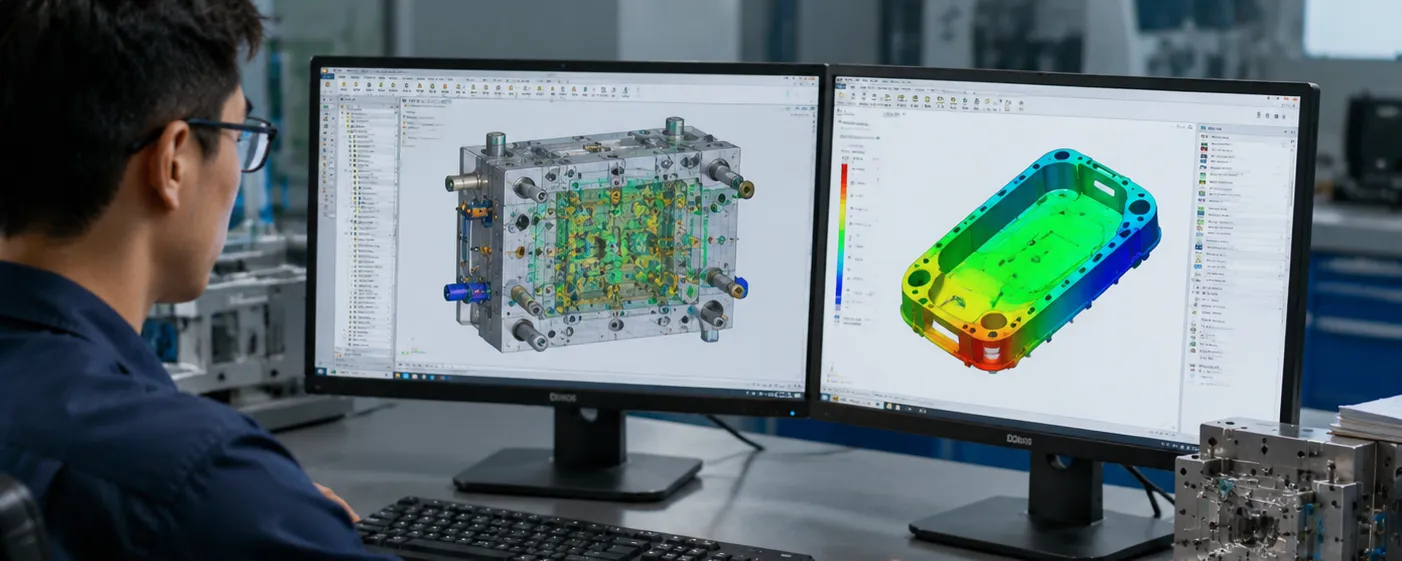
8. Define Tolerances by Function
Do not assign extreme tolerances to every dimension. Mark the dimensions that control sealing, bearing fits, alignment, assembly or safety. Other dimensions can often use standard molding tolerances. During prototype evaluation, compare critical dimensions after the part has reached a stable condition, especially for moisture-sensitive engineering plastics. The case study page is a useful internal destination for examples of molded prototype validation.
Additional Planning Consideration
For prototype parts, steel-safe thinking is useful. Where possible, uncertain dimensions can be designed so that material may be removed from the tool after the first trial rather than requiring steel to be added back. This does not solve every change, but it can make dimensional tuning faster and more controlled. The mold designer should identify these adjustment areas during the DFM discussion rather than after the first samples arrive.
Practical Project Tip
Before tooling approval, hold a short review with design, manufacturing, quality and purchasing. Confirm the drawing revision, resin, quantities, critical dimensions, cosmetic requirements, expected tool life and approval process. This simple cross-functional check prevents many quotation and tooling changes caused by different teams working from different assumptions.
Conclusion
A good prototype mold design produces more than a few acceptable samples; it produces trustworthy engineering evidence. Confirm pull direction, draft, wall thickness, ribs, undercuts, gating, venting, ejection, cooling and critical tolerances before the mold is released for machining. This reduces tool rework and prevents production problems from being mistaken for part-design problems. The FAQ explains the project information typically needed for quotation, and the contact page can be used to submit drawings for a DFM-oriented tooling review.