

Injection Mold Temperature Control Guide: Cooling, Warpage & Cycle Time
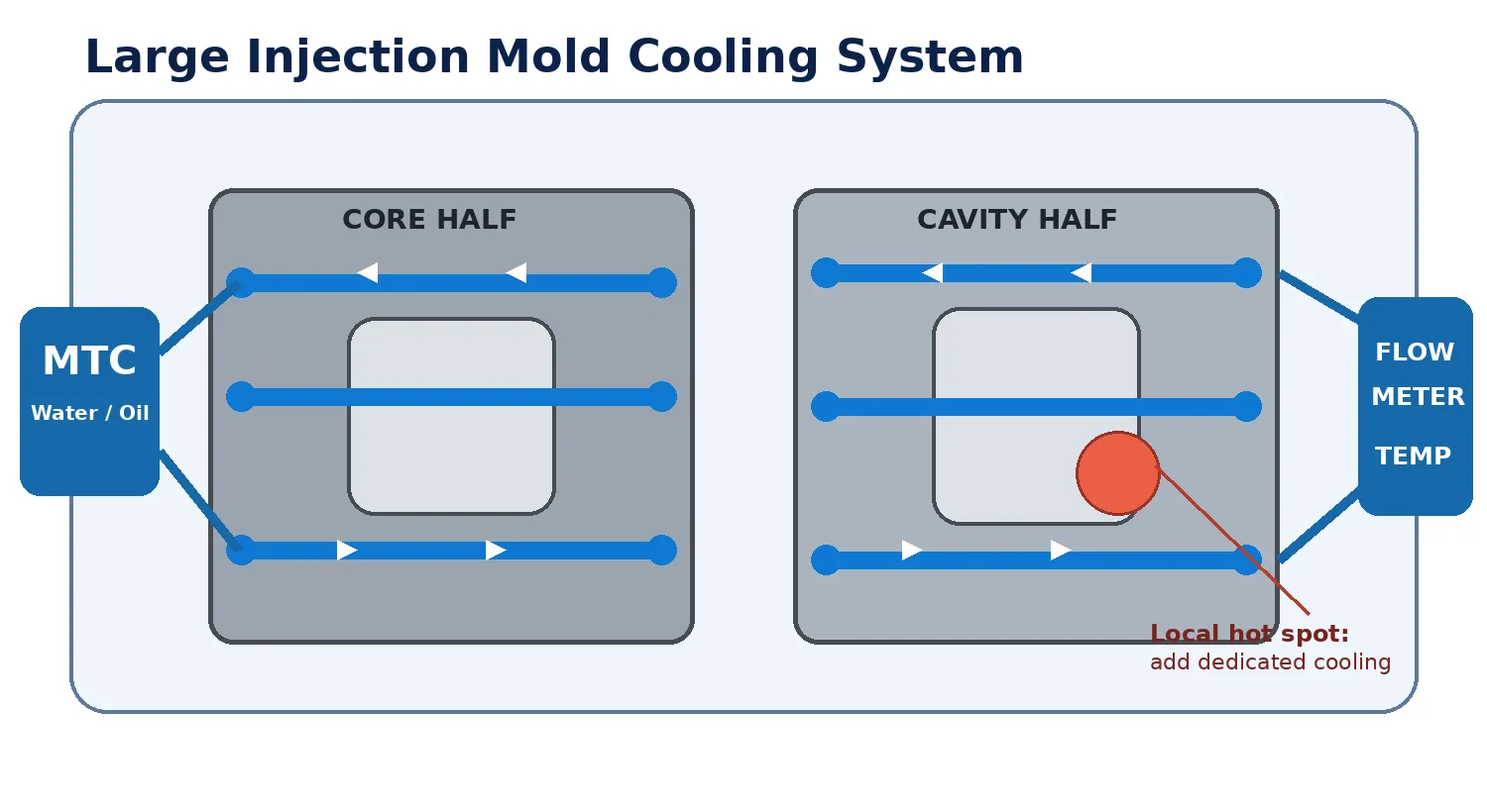
Temperature control is one of the most important factors in large injection molding. When a mold is large, complex, or equipped with multiple cavities, sliders, inserts, and deep cooling circuits, even a small temperature imbalance can create serious quality problems. Warpage, sink marks, short shots, inconsistent gloss, weld lines, dimensional variation, and long cycle times are often related to poor mold temperature management.
Large injection molds are commonly used for automotive panels, appliance housings, industrial enclosures, medical equipment covers, logistics products, furniture components, and other large plastic parts. These molds require carefully designed heating and cooling systems to maintain stable production conditions.
Why Mold Temperature Control Matters
Mold temperature affects nearly every stage of the injection molding process. After molten plastic enters the cavity, heat transfers from the resin into the mold. The mold must then remove this heat at a controlled rate before the part can be ejected. If the mold is too cold, the material may freeze before the cavity is completely filled, causing short shots, weak weld lines, poor surface replication, high internal stress, and visible flow marks. If the mold is too hot, cooling time may become excessive and parts may deform during ejection or stick to the cavity.
The objective is not simply to make the mold as cold as possible. The correct objective is to maintain a stable, uniform, and material-appropriate mold temperature throughout production.
Companies developing large plastic components should address thermal performance during tooling. Professional prototype and production mold services can help integrate cooling-channel planning, tooling strategy, and trial validation earlier in the project.
Challenges of Temperature Control in Large Injection Molds
Large molds are more difficult to control than small molds because heat must travel across a larger steel structure. Different areas cool at different rates depending on wall thickness, cavity depth, inserts, ribs, bosses, local material flow, and the position of moving components.
Uneven cooling between the core and cavity
Long water lines with high pressure loss
Hot spots near thick sections
Insufficient cooling near deep ribs and bosses
Temperature differences between moving and fixed mold halves
Poor flow through small or blocked cooling channels
Heat accumulation around sliders and lifters
Cooling imbalance between multiple cavities
Condensation when chilled water is used
Temperature drift during long production runs
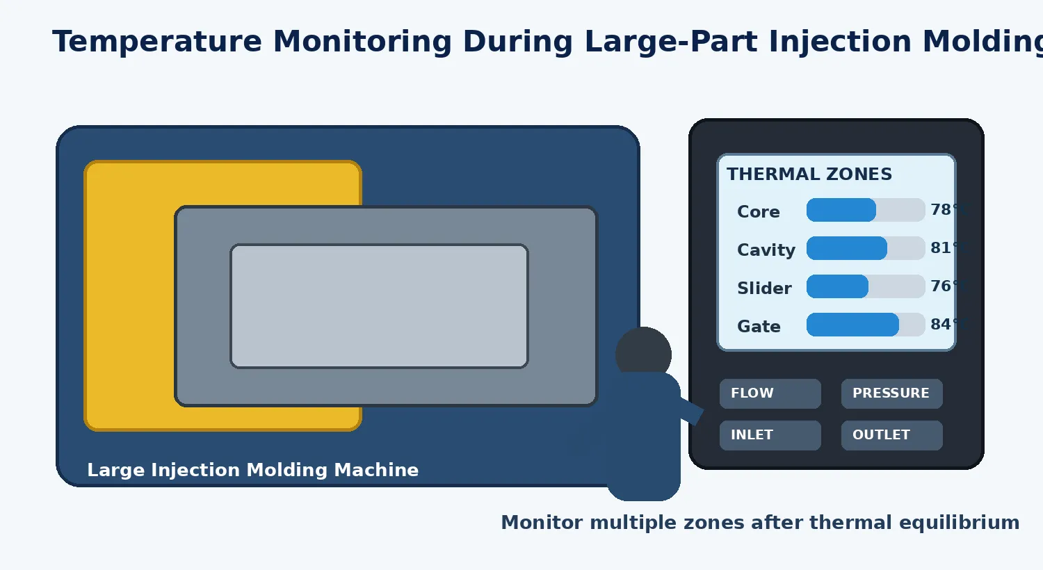
A large mold may appear acceptable during the first few cycles but become unstable as heat accumulates. For this reason, engineers should evaluate temperatures only after the system reaches thermal equilibrium.
How Mold Temperature Affects Part Quality
Warpage
Warpage often results from uneven shrinkage. If one side of a part cools faster than the other, the two sides contract at different rates. Large flat components are especially sensitive because small differences in shrinkage can create visible bending or twisting.
Sink Marks and Voids
Thick sections require more time to cool. If the surface freezes while the internal material remains hot, the part may continue shrinking beneath the surface, causing sink marks or internal voids.
Weld-Line Strength
A higher mold temperature can help separate flow fronts remain hot enough to bond more effectively. A mold that is too cold may create weak or highly visible weld lines.
Surface Finish
Gloss, texture replication, flow marks, and visible fiber patterns are influenced by cavity-surface temperature. Inconsistent cavity temperature may create different appearance levels across the same part.
Dimensional Accuracy
Parts molded under unstable temperature conditions may show significant dimensional variation. Stable temperature improves repeatability from cycle to cycle and between production batches.
Cycle Time
Cooling is often the longest stage of the molding cycle. An efficient cooling system can reduce production time without sacrificing part quality.
Manufacturers moving from design validation to repeatable molding can combine temperature optimization with professional plastic injection molding services.
Recommended Mold Temperature by Material
The correct mold temperature depends on the resin grade, part geometry, surface requirements, and dimensional expectations. Typical starting ranges are listed below, but the resin supplier's processing recommendations should always be reviewed.
Material | Typical Mold Temperature |
ABS | 40°C to 80°C |
Polypropylene | 20°C to 60°C |
Polyethylene | 20°C to 60°C |
Polycarbonate | 80°C to 120°C |
Nylon | 60°C to 100°C |
POM | 60°C to 100°C |
PMMA | 50°C to 90°C |
PBT | 60°C to 100°C |
PC/ABS | 60°C to 100°C |
Large parts may require a higher mold temperature to improve flow, surface quality, and weld-line strength. However, the higher temperature must be balanced against cooling time and ejection stability.
Cooling Channel Design for Large Molds
Channel Diameter
Cooling channels must be large enough to provide adequate flow while fitting safely within the mold structure. Very small channels create excessive pressure loss and can become blocked by scale or contamination.
Distance from the Cavity
Channels should be close enough to remove heat efficiently but far enough away to maintain mold strength and avoid visible temperature patterns on the part surface.
Uniform Spacing
Uniform spacing helps maintain even cooling. Widely spaced channels can create hot zones between circuits.
Parallel vs. Series Circuits
Long series circuits may create a large temperature difference between inlet and outlet. Parallel circuits provide more even cooling but require balanced flow. Multiple independent zones are often preferable for large molds.
Core Cooling
Deep cores are difficult to cool with conventional straight drilling. Baffles, bubblers, spiral channels, thermal pins, and conformal cooling inserts may be required.
Slider and Lifter Cooling
Large sliders and lifters can retain heat and create local defects. Dedicated cooling lines may be needed when these components contact thick molded sections.
Conformal Cooling
Conformal channels follow the cavity shape more closely than traditional straight-drilled passages. They can improve temperature uniformity around complex geometry, although tooling cost and manufacturing complexity may increase.
A complete one-stop product development process can coordinate part design, DFM analysis, mold engineering, simulation, and production planning before tooling begins.
Temperature-Control Equipment
Mold Temperature Controllers
A mold temperature controller circulates heated water or oil through the mold and maintains a selected temperature. Water-based systems are common at moderate temperatures, while oil-based systems are used at higher temperatures. The controller must provide sufficient heating power, cooling capacity, pump pressure, and flow rate.
Industrial Chillers
Chillers provide low-temperature water for rapid heat removal. They are useful for high-output production but must be used carefully to avoid condensation and excessive thermal shock.
Central Cooling Systems
Large factories may use cooling towers or chilled-water systems to support multiple machines. Local flow and temperature still need to be monitored at each mold.
Flow Meters
Flow meters show whether each circuit receives adequate coolant. They help identify blocked channels, incorrect valve settings, air pockets, and circuit imbalance.
Temperature Sensors
Surface thermocouples, infrared cameras, contact probes, and embedded sensors can measure mold temperature. Large molds should be measured at multiple locations rather than at a single point.
Importance of Turbulent Flow
Effective cooling depends not only on coolant temperature but also on flow condition. Turbulent flow improves heat transfer because coolant moves actively across the channel wall. Laminar flow creates a stable boundary layer that reduces cooling efficiency. Flow behavior depends on channel diameter, velocity, viscosity, and temperature. A circuit with very cold water but insufficient flow may remove less heat than a slightly warmer circuit with strong turbulent flow.
Using Thermal Simulation
Mold cooling simulation can predict temperature distribution before the tool is manufactured. It may reveal slow-cooling areas, hot spots near thick sections, imbalance between core and cavity, inadequate channel spacing, excessive inlet-to-outlet temperature change, uneven cooling between cavities, and potential warpage. Simulation is especially valuable for large parts because tooling modifications after completion can be expensive and time-consuming.
Companies can reduce development risk by combining thermal analysis with industrial product design and engineering during early product development.
Startup and Process Stabilization
Large molds require more time to reach stable operating temperature. Before production begins, the mold should be preheated to the target temperature. Starting with a cold mold can lead to inconsistent parts during the first several cycles.
Connect and check all cooling circuits.
Confirm that valves are open and flow direction is correct.
Start the temperature controller.
Allow the mold to approach the target temperature.
Run initial molding cycles.
Monitor inlet and outlet temperatures.
Measure cavity and core surface temperatures.
Adjust individual zones if necessary.
Wait until dimensions and part weight stabilize.
Record the final process conditions.
Troubleshooting Common Temperature Problems
One Area of the Part Is Warped
Possible causes include a local hot spot, blocked cooling line, excessive wall thickness, unbalanced packing, or uneven core and cavity temperature. Compare local surface temperature and coolant flow.
Cycle Time Is Too Long
Channels may be too far from the cavity, flow may be insufficient, or outlet water temperature may be too high. Improving flow, cleaning channels, separating long circuits, or adding local cooling may reduce cycle time.
Surface Gloss Is Inconsistent
Different cavity areas may have different surface temperatures. Verify circuit layout, coolant flow, and actual mold-surface temperature.
Weld Lines Are Weak
The mold may be too cold near the flow-front meeting area. Increasing local temperature or modifying gate position may improve bonding.
Parts Stick to the Mold
The mold may be too hot at ejection, cooling time may be insufficient, or draft and surface finish may need improvement.
Water Flow Is Unstable
The circuit may contain air, scale, rust, debris, or an incorrectly connected hose. Flush the circuit and inspect pump and valve settings.
Cooling Water Quality and Maintenance
Cooling channels gradually lose efficiency if scale, rust, oil, or biological contamination builds up inside them. Poor water quality can reduce channel diameter and create an insulating layer on the steel surface, increasing cycle time and reducing process stability.
Regular channel flushing
Water filtration and corrosion protection
Scale removal
Leak inspection
Flow-rate checks
Hose and connector inspection
Temperature-controller maintenance
Recording inlet and outlet pressure
Cleaning before long-term mold storage
Separate Temperature Zones and Hot Runner Coordination
Large molds should often be divided into independent zones such as the fixed half, moving half, core area, cavity area, sliders, thick-section areas, gate area, individual cavities, hot runner manifold, and large inserts. Separate zones allow engineers to correct local hot or cold areas without changing the temperature of the entire tool.
When a hot runner system is used, its temperature must be coordinated with the mold temperature. If the hot runner is too hot, resin may degrade, drool, or string. If it is too cold, pressure may increase and filling may become unstable. Gate areas can also become local hot spots, so cooling around the nozzle and gate must be designed carefully.
Reducing Energy Consumption
Insulate the mold from the machine platen.
Repair leaking hoses and fittings.
Use appropriately sized pumps.
Avoid unnecessarily low coolant temperatures.
Clean channels to improve heat transfer.
Preheat the mold efficiently.
Reduce idle circulation when production stops.
Separate high-temperature and low-temperature zones.
Monitor actual energy consumption.
Optimize cooling time based on part temperature rather than habit.
Quality Control and Process Documentation
Temperature-control settings should be included in the standard molding process sheet. Important records include controller set temperature, actual inlet temperature, outlet temperature, flow rate, pressure, hose layout, cooling circuit number, mold-surface temperature, startup stabilization time, cycle time, cooling time, part weight, critical dimensions, ambient temperature, and resin drying conditions.
Before mass production, teams may also use injection molded prototype services to validate part performance, mold behavior, and thermal stability with smaller quantities.
Best Practices
Design cooling channels early in the mold engineering process.
Divide large molds into independent temperature zones.
Use adequate channel diameter and flow rate.
Avoid excessively long series circuits.
Monitor inlet and outlet temperature.
Measure actual mold-surface temperature.
Preheat the mold before production.
Wait for thermal equilibrium before approving parts.
Maintain clean cooling water.
Inspect circuits during preventive maintenance.
Record all temperature and flow settings.
Use simulation for complex parts.
Coordinate mold temperature with resin recommendations.
Check local cooling near thick sections.
Review cooling performance after design changes.
Conclusion
Large injection mold temperature control is essential for stable quality, accurate dimensions, good surface appearance, and efficient production. Because large molds contain more steel, longer cooling circuits, complex moving components, and larger molded surfaces, they require a carefully planned thermal-management strategy.
Successful control begins with product design and continues through DFM analysis, mold engineering, cooling circuit design, equipment selection, trial molding, maintenance, and process documentation. A uniform mold temperature helps reduce warpage, improve weld-line strength, shorten cycle time, and maintain consistency between batches.
For large plastic components, mold temperature should not be treated as a minor machine setting. It is a complete engineering system that directly influences product quality, tooling performance, energy consumption, and manufacturing cost.