

A prototype injection mold can be manufactured quickly, but speed should not replace engineering discipline. When a precision plastic part enters tooling with avoidable design problems, the project can lose time through mold corrections, unstable processing, and repeated sample reviews. A focused design for manufacturability, or DFM, review helps remove those risks before machining begins.
DFM is not about redesigning a product for the convenience of the mold maker. Its purpose is to make sure function, appearance, tolerance, material, and manufacturing can work together. This is especially important for automotive structural parts, medical-device housings, communication equipment, and precision industrial components. HPDI's engineering and prototype molding services support this review before mold fabrication.
1. Define What the Prototype Must Prove
Before reviewing geometry, identify the validation objective. The molded parts may need to confirm fit, sealing, impact performance, resin behavior, surface quality, dimensional capability, or assembly stability.
A mold for visual samples can be simpler than a tool used for repeated functional tests. Critical features should be marked on the drawing so the supplier can protect them during gate, parting-line, cooling, and ejector planning. Reviewing application examples can also help the team define practical acceptance criteria.
2. Control Wall Thickness
Uniform wall thickness supports balanced filling and cooling. Thick sections cool slowly and may create sink or internal voids, while thin areas may hesitate or fail to fill. When thickness must change, use gradual transitions. Strength should usually be added with ribs or local geometry rather than making the complete wall heavier.
Feature | Main Risk | Better Direction |
Abrupt thick-to-thin transition | Sink and differential shrinkage | Use a gradual transition |
Heavy boss on a cosmetic wall | Visible depression | Core the boss and support it with ribs |
Long thin flow section | Short shot or high pressure | Review thickness and gate location |
Large flat panel | Warpage | Add controlled stiffness |
3. Provide Sufficient Draft
Draft is the taper that allows a molded wall to release from the tool. Insufficient draft increases friction during ejection and can cause drag marks, texture damage, deformation, or sticking.
The required angle depends on depth, resin, polish, texture, and shrinkage direction. Textured surfaces usually need more draft than polished surfaces. The designer should identify the core side, cavity side, cosmetic zones, and deep features, then confirm the requirement with the mold engineer.
4. Design Ribs and Bosses Carefully
Ribs increase stiffness without making the entire wall thick, but heavy ribs can create sink marks. Tall, thin ribs may also be difficult to fill, vent, and polish.
Bosses for screws or inserts need enough support to resist loading, but they should not become isolated masses of plastic. Connecting ribs improve strength, while coring the center reduces cooling imbalance.
5. Plan Undercuts Deliberately
Undercuts require sliders, lifters, collapsible cores, removable inserts, or a design change. Every mechanism adds cost, lead time, wear surfaces, and maintenance.
Some undercuts are essential for clips, windows, or connector locks. Others can be removed by changing the parting line or redesigning the feature for straight pull. A manual insert may reduce prototype-tool cost, but the team should consider handling time and repeatability.
6. Choose the Gate Around Function and Appearance
The gate controls where molten resin enters the cavity. Its position affects flow length, weld lines, pressure, fiber orientation, shrinkage, and the visible gate mark.
Gate selection should consider cosmetic zones, sealing surfaces, assembly interfaces, thick sections, and the end-of-fill location. For reinforced materials, gate direction can affect fiber orientation and warpage. Mold-flow simulation may be useful when a part has long flow paths, varying thickness, multiple gates, or strict dimensional requirements.
7. Plan Ejection, Venting, and Cooling
Ejector pins need supported locations where their force will not distort the part or damage a visible face. Venting allows trapped air and gases to escape. Poor venting can cause burns, short shots, or weak weld lines.
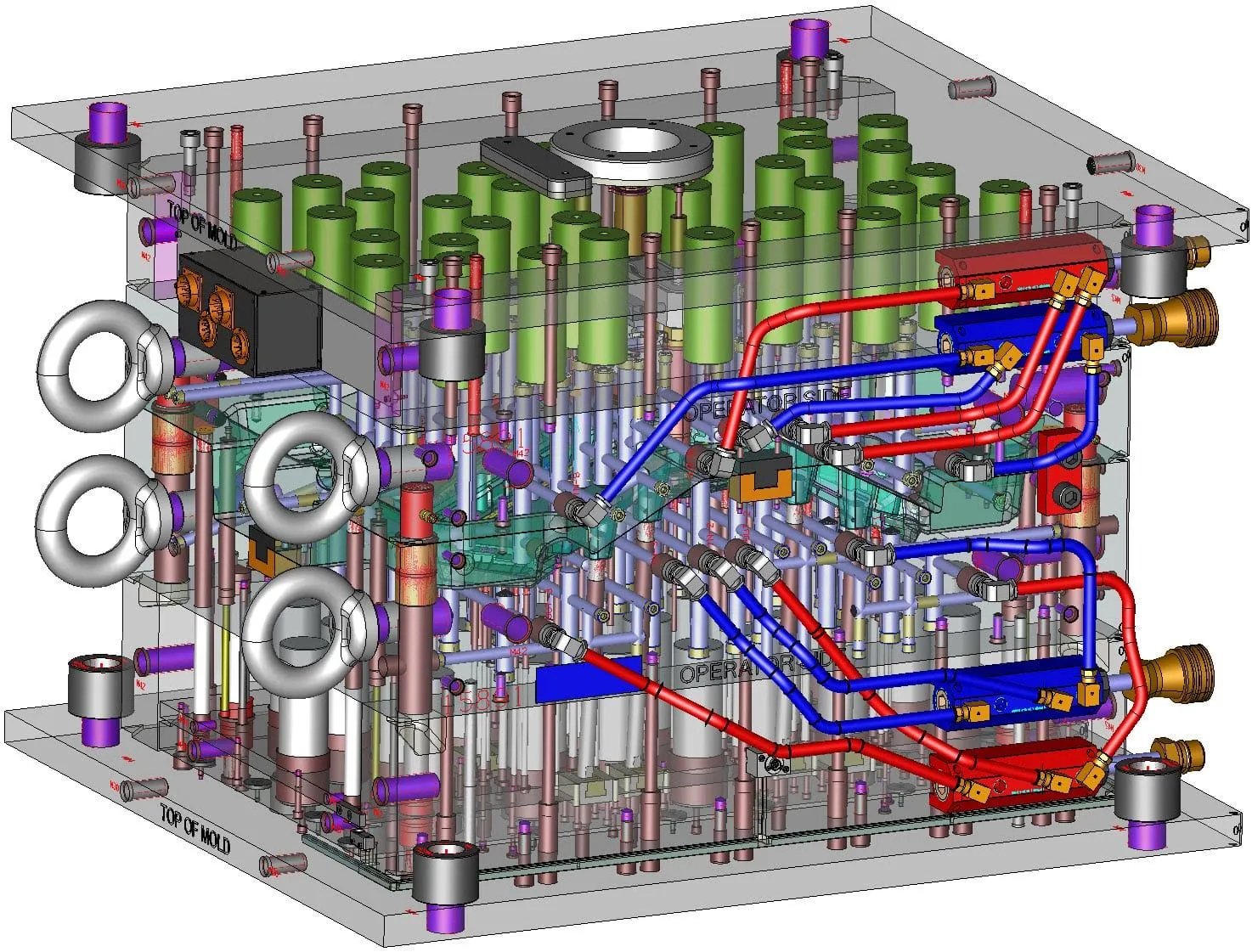
Cooling channels should target thick areas, long cores, and regions that influence flatness. A supplier with in-house mold design, CNC, EDM, injection molding, and inspection equipment can coordinate these details more effectively. The facilities page outlines available mold fabrication and measurement equipment.
8. Match Tolerances to Function
Over-tolerancing increases machining, inspection, and adjustment effort without always improving the product. Each tight dimension should be linked to a functional need such as sealing, alignment, motion, or assembly.
Resin shrinkage, moisture, fiber orientation, cooling balance, and measurement conditions can influence the final result. Critical-to-quality features, datums, inspection methods, and conditioning requirements should be defined before release.
9. Complete a Formal Review
The final DFM review should include product engineering, mold design, molding, quality, and project management. Decisions about resin, shrinkage, parting line, gates, ejectors, slides, inserts, texture, dimensions, and sample quantity should be documented.
The FAQ explains the files and information normally needed for quotation, including 3D data, drawings, resin, mold requirements, lead time, and expected shots. Providing this information early improves both the DFM review and quotation accuracy.
Conclusion
A prototype mold is most effective when it begins with a clear validation objective and a disciplined DFM checklist. Controlled walls, suitable draft, well-designed ribs and bosses, deliberate undercuts, thoughtful gating, balanced ejection, adequate venting, and functional tolerances all contribute to stable molded samples.
DFM does not remove the need for mold trials. It makes those trials informative by reducing avoidable geometry problems. Teams ready to review a precision plastic part can submit CAD data and requirements through the contact page for an initial engineering assessment.
Copyright 2026(C) HUAWEI PRODUCT DEVELOPMENT INDUSTRIAL LTD (2009-2024)
All Rights Reserved
marketing@prototypeinjectionmold.com
Contact Information :
Byron Wang
Phone: +86- 86-755-8238-2595
Mobile: +86-139-2383-5403
Email: marketing@prototypeinjectionmold.com
HPDI (HUAWEI PRODUCT DEVELOPMENT INDUSTRIAL LTD)
Adress:Building 3, Puxia Industrial Zone, Liuyue, Henggang St., Longgang District, Shenzhen., China