

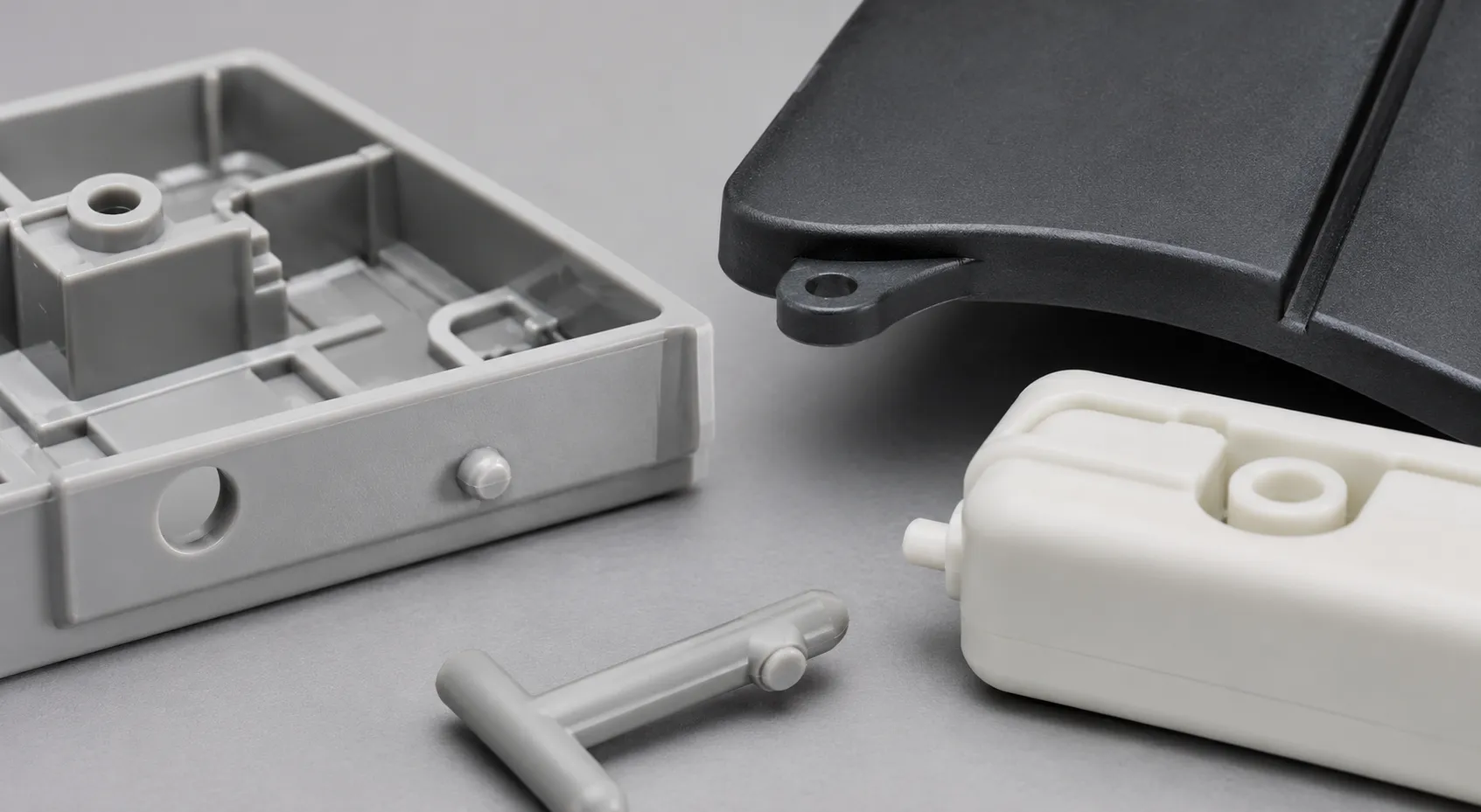
The gate is the opening through which molten plastic enters the mold cavity. It may be small, but its position influences almost every result that matters: filling pressure, weld-line location, trapped air, packing, shrinkage, fiber orientation, gate vestige, and ejection behavior. In prototype injection molding, the gate should not be placed only where the tool is easiest to build. It should help the sample reproduce the risks that the product team needs to understand before production.
Molded samples from prototype injection molding services are most valuable when the flow path is relevant to the intended product. If the future production mold is expected to fill from a particular side or use a similar gate type, matching that direction during prototype trials can reveal functional weaknesses that a visually acceptable sample might hide.
Start With the End of Fill
A practical gate review begins by predicting where flow fronts will meet and where filling will finish. Weld lines often form around holes, bosses, ribs, windows, and multiple flow paths. Their location matters because the bonded material can be weaker than uninterrupted flow, especially in impact-loaded clips, pressure housings, or thin structural sections. If a weld line lands on a cosmetic face or critical feature, the gate position may need to move.
The end of fill is also a common place for trapped gas. Without adequate venting, compressed air can cause burns, short shots, weak bonding, or unstable dimensions. Gate location and venting should therefore be reviewed together. A mold that pushes air into a blind pocket cannot be corrected reliably by increasing pressure alone.
Balance Pressure, Packing, and Appearance
Gating into a thick section can support packing and reduce the risk of freezing too early, but the gate mark may become more visible. Gating into a thin edge can protect appearance yet create high shear or a long, difficult flow path. The team must rank what is most important: mechanical strength, surface quality, dimensional control, cycle behavior, or similarity to the planned production tool.
Large flat parts and long housings need special attention because uneven packing can contribute to warpage. Multiple gates may shorten flow length, but they create additional weld lines and balancing work. A single gate may simplify the prototype tool while placing excessive pressure on the resin. The right solution depends on wall thickness, material viscosity, geometry, and the acceptance criteria listed in the prototype molding FAQ.
Filled Resins Make Flow Direction More Important
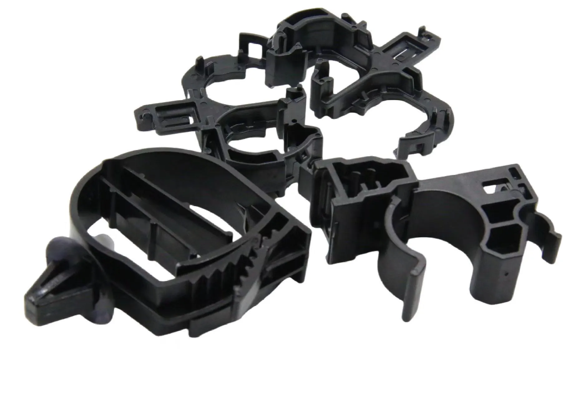
Glass fibers and other reinforcements tend to align with the direction of flow. That orientation can improve stiffness in one direction while increasing shrinkage differences and warpage in another. Two parts made from the same resin and geometry can perform differently when the gate changes. For a reinforced bracket, housing, or structural frame, gate strategy should be connected to the load direction and dimensional test plan.
This is one reason machined or printed prototypes cannot answer every development question. They do not reproduce the same fiber orientation, weld lines, packing history, or gate-area stress. Reviewing relevant case study examples can help teams define which features must be tested using actual molded parts.
Plan the Gate Vestige and Removal Method
Every gate leaves evidence. A trimmed edge gate, pin gate, tab gate, fan gate, or submarine gate creates a different mark and removal process. The vestige must not interfere with sealing, assembly, sliding contact, labels, or visible surfaces. If automatic degating is not required for a short prototype run, a manually trimmed gate may simplify tooling, but the trimming standard should still be defined.
Before mold design approval, mark prohibited gate areas on the 3D model or drawing. Identify critical load paths, cosmetic zones, sealing surfaces, and mating features. Also state whether the prototype should imitate the future production gate or simply provide functional samples quickly. Teams can contact HPDI to review the proposed flow direction, expected weld-line areas, and practical gating options before steel is machined.
Validate the Gate With Staged Samples
Do not approve gating from one attractive part. Compare samples across a stable process window and inspect the end of fill, weld lines, gate area, and critical dimensions. For structural parts, test pieces should be taken from clearly identified process groups so a strength result can be linked to molding conditions. If the gate is manually trimmed, inspect several operators or trimming cycles to confirm the vestige remains within the drawing limit.
When a change is needed, record the original gate, reason for the change, expected effect, and measurements used for approval. This preserves useful learning for the production mold. It also prevents a later team from restoring a convenient gate position that was already shown to create a weak line, air trap, or unacceptable mark.
Frequently Asked Questions
Can process settings remove a badly placed weld line? Settings can improve bonding, but they cannot always move a weld line away from a critical feature. Geometry and gate position remain fundamental.
Should the prototype gate match production? When flow-dependent strength, warpage, or appearance is being validated, matching the intended direction is valuable. For basic fit checks, a simpler gate may be acceptable.
What should a customer approve? Approve the gate type, gate location, expected vestige, likely weld-line zones, and any manual trimming requirement.
Copyright 2026(C) HUAWEI PRODUCT DEVELOPMENT INDUSTRIAL LTD (2009-2024)
All Rights Reserved
marketing@prototypeinjectionmold.com
Contact Information :
Byron Wang
Phone: +86- 86-755-8238-2595
Mobile: +86-139-2383-5403
Email: marketing@prototypeinjectionmold.com
HPDI (HUAWEI PRODUCT DEVELOPMENT INDUSTRIAL LTD)
Address:Building 3, Puxia Industrial Zone, Liuyue, Henggang St., Longgang District, Shenzhen., China