

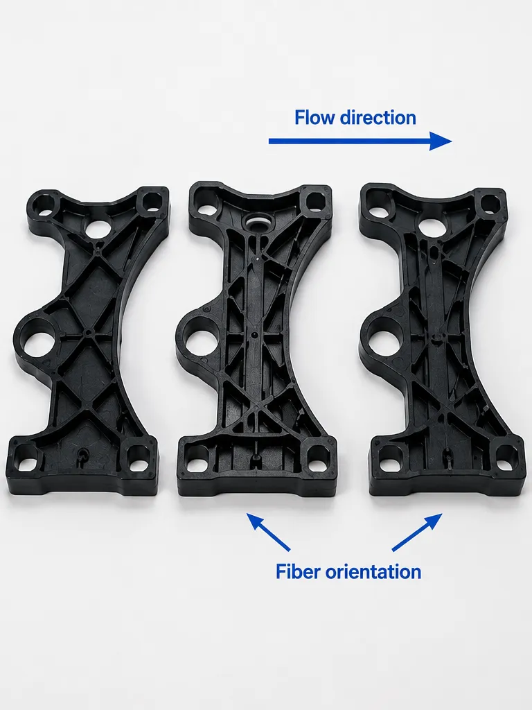
Warpage Is a Symptom, Not a Single Defect
A molded part that rocks on a flat surface, twists during assembly, or misses a hole position may be described simply as warped. That description is useful for inspection, but it does not identify the cause. Warpage can come from uneven wall thickness, nonuniform cooling, molecular or fiber orientation, gate location, packing differences, ejection stress, or a combination of these factors. Changing steel before separating those causes can waste time and create a second problem.
Prototype tools make this investigation possible while the design is still adjustable. Through prototype injection molding services, teams can compare production-intent materials, controlled process settings, and measured samples before final production tooling decisions are locked.
Measure the Part in a Repeatable Condition
The first step is to define how and when the part is measured. Plastics continue to cool and may absorb moisture after molding. A nylon component measured immediately after ejection can differ from the same component after conditioning. A thin housing placed on an uneven table can also appear worse than it is. Use a stable fixture, agreed datums, a controlled conditioning period, and a drawing that identifies the dimensions that matter to function.
Record cavity number, molding date, resin lot, and process condition for each sample group. The goal is not to collect data for its own sake. It is to determine whether the distortion is consistent, process-sensitive, cavity-specific, or random. HPDI's manufacturing facilities include machining, molding, and inspection resources that support this kind of connected review.
Separate Design-Driven and Process-Driven Patterns
Design-driven warpage often follows the geometry. Thick-to-thin transitions, heavy bosses, asymmetric ribs, open box sections, and large unsupported faces cool and shrink at different rates. Adding more packing pressure may reduce sink while increasing stress elsewhere. A geometry correction may involve coring a heavy area, balancing rib layout, improving wall transitions, adding a temporary support feature, or changing a datum strategy.
Process-driven warpage often changes when packing, mold temperature, melt temperature, cooling time, or ejection timing changes. That does not mean the design is automatically acceptable. A very narrow process window is a warning for production. Prototype trials should look for a stable range that produces acceptable parts, not a single exceptional cycle that passes inspection once.
Consider Material Orientation and Shrinkage
Unfilled polymers shrink differently according to flow history and local packing. Reinforced materials add stronger directional behavior because fibers align with flow. Gate position can therefore change which direction becomes stiff and which direction shrinks more. If the prototype tool fills differently from the future production mold, the warpage result may not transfer.
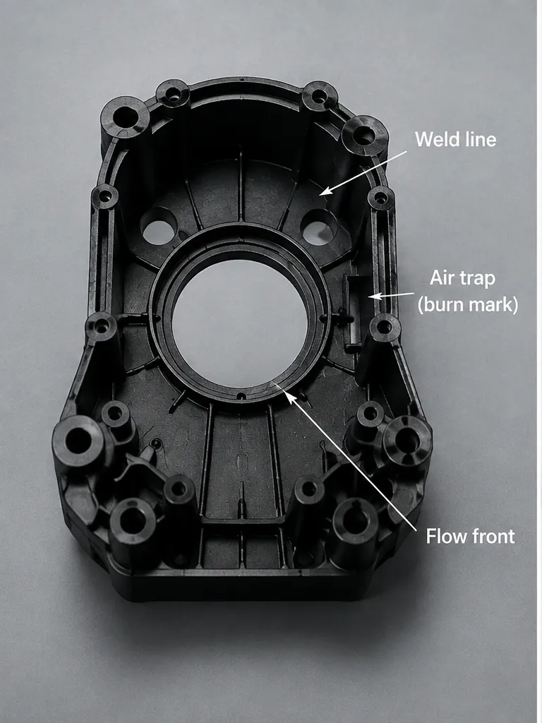
Compare the observed shape with the predicted flow path. A repeatable bow downstream from the gate, twist around an asymmetric rib network, or movement near a weld line provides clues. Molded case study examples are useful references because they show the type of real geometry, not only simple test plaques, that development teams need to evaluate.
Use a Controlled Correction Order
Begin with the least permanent variables. Confirm material drying and conditioning, then establish stable temperatures, filling, packing, cooling, and ejection. Next, inspect cooling balance, venting, gate behavior, and part release. Only after the pattern is understood should the team decide whether to adjust steel or revise product geometry. Change one main variable at a time and keep sample groups clearly labeled.
The approval criterion should be functional. A slight free-state curve may be acceptable if the part assembles without force and holds critical interfaces. A visually flat sample may still contain stress that appears after heat exposure. More technical articles on molded-part validation are available in the HPDI News & Blog, but every project should define its own flatness, assembly, and environmental requirements before sampling.
Test Beyond the Inspection Table
Warpage should be evaluated in the condition where the product works. Assemble the part with its real fasteners, seals, clips, and mating components. Measure gaps and insertion forces, then repeat the check after the environmental exposures required by the program. Heat, humidity, chemical contact, vibration, or repeated fastening can release molded-in stress and reveal movement that was not visible at room temperature.
Use photographs or scan data to compare the deformation shape before and after testing. If assembly force pulls the part flat, confirm that the load does not distort another component or reduce seal compression. If the part relaxes into an acceptable position after conditioning, document that state rather than relying on memory. These observations help the team decide whether the drawing should control free-state geometry, restrained assembly geometry, or both.
A correction is successful only when it improves the required condition without creating a new problem. Recheck sink, weld lines, dimensions, ejection marks, and cycle stability after any major geometry, gate, cooling, or process change.
Frequently Asked Questions
Can longer cooling always fix warpage? It can help when ejection occurs too early, but it cannot fully correct unbalanced geometry, orientation, or cooling channels.
Should warped parts be clamped during measurement? Only if the drawing defines a restrained condition. Otherwise, clamping can hide the distortion the assembly will experience.
When is steel adjustment justified? After repeatable measurements and controlled trials show that processing alone cannot meet the functional requirement.
Copyright 2026(C) HUAWEI PRODUCT DEVELOPMENT INDUSTRIAL LTD (2009-2024)
All Rights Reserved
marketing@prototypeinjectionmold.com
Contact Information :
Byron Wang
Phone: +86- 86-755-8238-2595
Mobile: +86-139-2383-5403
Email: marketing@prototypeinjectionmold.com
HPDI (HUAWEI PRODUCT DEVELOPMENT INDUSTRIAL LTD)
Address:Building 3, Puxia Industrial Zone, Liuyue, Henggang St., Longgang District, Shenzhen., China