

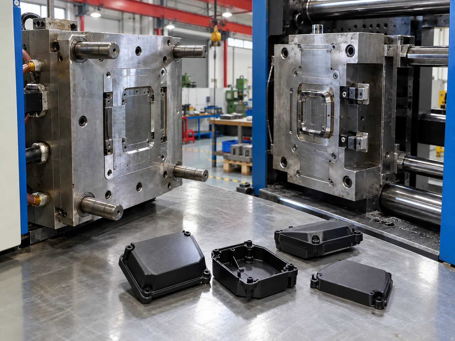
The first meaningful injection-molded samples often reveal more about a plastic part than weeks of CAD review. A T1 trial brings the part design, selected resin, gate location, cooling, ejection and mold construction together for the first time. The objective should not be to declare the design “finished” after one shot; it should be to identify which risks need correction before the project advances.
Prototype injection molds are well suited to this task because they can be simplified around the validation objective. HPDI provides prototype molds, aluminum molds and bridge tooling within its injection molded prototype service, allowing changes to be made before complex production tooling is locked in.
What should a T1 trial actually prove?
A useful T1 trial answers four separate questions. First, can the cavity fill and eject the part? Second, does the molded part match the intended geometry closely enough for meaningful inspection? Third, does the selected resin behave as expected in the real component? Fourth, are the mold concept and part design suitable for further development?
The team should avoid treating cosmetic appearance as the only acceptance criterion. A part can look good but still have hidden dimensional drift, poor assembly fit, weak weld lines or excessive molded-in stress.
Why use a simplified mold instead of a production mold?
A production mold may include multiple cavities, automation, long-life wear components and optimized cooling intended for stable volume manufacturing. Those features can be unnecessary when the design is still being validated. A simplified tool can use a single cavity, standard components, manual inserts or replaceable local inserts while still producing real injection-molded parts.
This reduces the number of variables the team must change if T1 exposes a problem. The existing DFM checklist is a useful pre-tooling step because it helps identify likely wall-thickness, draft, undercut and ejection issues before metal is cut.
What should be inspected after T1?
The inspection plan should focus on critical-to-function characteristics. Typical items include overall flatness, hole spacing, mating surfaces, snap-fit geometry, boss location, sealing areas and other dimensions tied directly to product performance. Cosmetic features such as gloss, visible weld lines or gate vestige should be checked against the intended product requirements rather than against a generic standard.
HPDI’s facilities include mold machining, injection molding and dimensional inspection resources, which supports quick comparison between the tool condition and molded-part measurements.
How do you separate tool problems from process problems?
T1 defects should be diagnosed systematically. A short shot may come from a restrictive gate, trapped air, material condition or process settings. Warpage may come from part geometry, gate orientation, cooling imbalance or fiber direction. Flash may indicate parting-line, shutoff or processing issues. The first response should not be to machine the mold immediately.
The molding team should first establish a stable process window and confirm that the defect repeats. Only then should the project decide whether the correction belongs in the part design, mold design or processing conditions.
What changes are easiest to plan into prototype tooling?
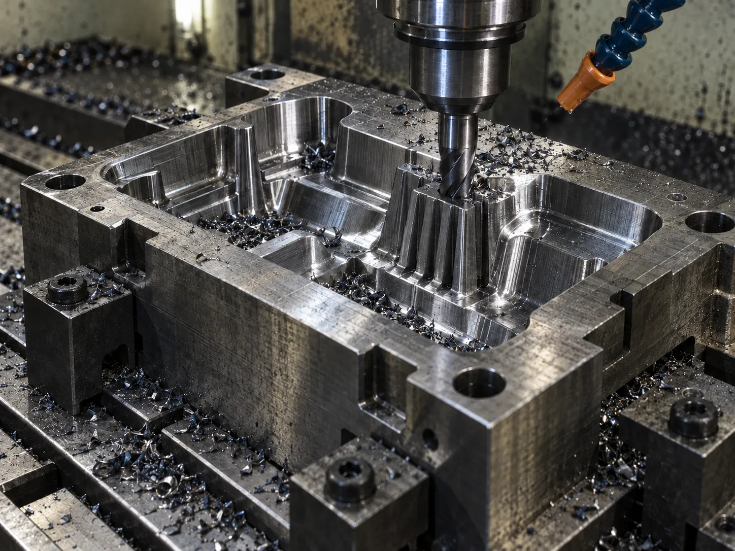
Areas likely to change after T1 should be designed for access. Replaceable inserts are useful around connectors, snap features, local ribs, sealing details and gate regions. Steel-safe dimensions can also preserve room for machining after the first measurement cycle. Aluminum tooling can be efficient when frequent local machining is expected, while simplified steel may be preferred when wear or repeated testing is more demanding.
For quotation and tooling-input guidance, the site’s prototype molding FAQ explains the information customers should prepare before a prototype mold is quoted and released.
T1 engineering validation checklist
Before closing the T1 review, confirm:
The approved resin and material condition are recorded.
The part fills and ejects consistently.
Critical dimensions have been measured.
Assembly fit has been tested where possible.
Cosmetic concerns are separated from functional concerns.
Root causes are assigned to design, tool or process.
Required changes are documented against a controlled CAD revision.
The next trial has clear acceptance criteria.
A T1 report does not need to be complicated, but it should make the next engineering decision unambiguous.
How should T2 decisions be made?
T2 should not repeat T1 without a clear reason. Each modification should have an expected effect and a measurable acceptance check. If a rib was reduced to address sink, compare the new surface and stiffness with T1. If a gate was adjusted, compare filling, weld-line position and dimensional response. If the customer changed a mating feature, verify the assembly rather than only the isolated dimension.
This discipline keeps the prototype program from becoming an open-ended cycle of changes. Once the critical functions, dimensions and molding behavior are stable, remaining cosmetic or production-efficiency improvements can be separated from the engineering validation decision.
Conclusion
Simplified prototype injection molds make T1 useful because they turn the first molded samples into engineering evidence. The value comes from controlled inspection, root-cause analysis and targeted changes, not from simply producing a visually acceptable part.
Teams preparing a T1 program can review HPDI’s related prototype validation article or send project drawings for a tooling and validation discussion.
Copyright 2026(C) HUAWEI PRODUCT DEVELOPMENT INDUSTRIAL LTD (2009-2024)
All Rights Reserved
marketing@prototypeinjectionmold.com
Contact Information :
Byron Wang
Phone: +86- 86-755-8238-2595
Mobile: +86-139-2383-5403
Email: marketing@prototypeinjectionmold.com
HPDI (HUAWEI PRODUCT DEVELOPMENT INDUSTRIAL LTD)
Address:Building 3, Puxia Industrial Zone, Liuyue, Henggang St., Longgang District, Shenzhen., China