

Warpage is difficult to judge from CAD alone because it is created by the interaction of geometry, material flow, packing and cooling. A flat digital model can leave the mold with a twist, bow or local distortion even when its nominal dimensions appear reasonable. This is one of the strongest reasons to use injection molding prototypes before releasing a production tool.
A simplified mold lets the team reproduce real injection molding conditions and evaluate the finished component rather than a theoretical shape. HPDI’s prototype injection molding service supports this type of validation with prototype molds, aluminum tooling and molded-part inspection.
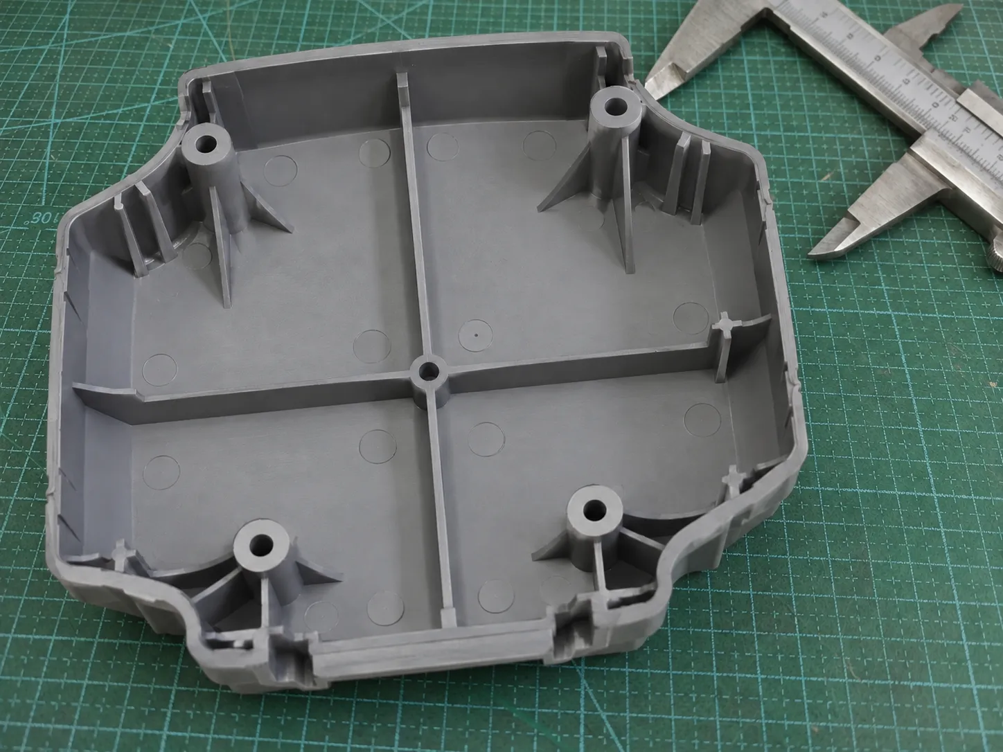
Why does a molded part warp?
Plastic shrinks as it cools. Warpage occurs when that shrinkage is not balanced throughout the part. A thick area may cool later than a thin wall. Ribs placed on one side of a panel can create local pull. A gate can orient material flow in a direction that changes shrinkage. The core and cavity can remove heat at different rates.
Reinforced materials add another variable because fibers tend to align with flow. The resulting shrinkage can be directional rather than uniform. For this reason, warpage should be treated as a system problem rather than as a single processing defect.
What geometry should be reviewed first?
Uneven wall thickness, large flat spans, asymmetrical ribs, heavy bosses and abrupt transitions are common risk areas. Engineers should ask whether stiffness can be created with better rib layout instead of thicker walls, whether a boss can be cored out and whether mirrored geometry can be made more balanced.
The existing DFM checklist for prototype injection-molded parts provides a useful pre-tooling review of these features. Correcting high-risk geometry in CAD is usually preferable to trying to process around it later.
How can gate location change distortion?
Gate position influences how the cavity fills and how pressure reaches different regions during packing. It also determines the main flow direction. A gate that creates a long, unbalanced flow path can leave one area under-packed or produce a strong directional effect in a fiber-filled resin.
Prototype tooling makes it possible to evaluate a practical gate concept before the production mold layout is fixed. If warpage follows the flow direction or changes after a gate adjustment, the team gains evidence that helps separate material orientation from general cooling effects.
Why does cooling need to be evaluated at the tool level?
Uniform cooling matters more than simply achieving a short cycle. If one side of the mold removes heat faster, the part can shrink unevenly. Deep cores, thick local sections and areas far from cooling passages can create hot spots. Aluminum tooling can transfer heat efficiently, but the cooling layout still needs to match the actual geometry.
HPDI’s existing guide on injection mold temperature control and warpage discusses the relationship between mold temperature, cooling stability and dimensional variation in more detail.
What should be measured on prototype parts?
Visual inspection can miss gradual bowing or twist. The validation plan should define how flatness or profile will be measured. Depending on the part, this may involve a CMM, a simple fixture, controlled gap measurement or assembly into the mating product. Measurements should be taken after the part has reached the intended conditioning state rather than immediately after ejection if the material continues to change.
HPDI’s facilities include dimensional inspection capability that can support repeated measurement after tool or process changes.
How should the team correct warpage?
The first correction should target the root cause. Geometry changes may include balancing ribs or removing local mass. Tool changes may include gate or cooling adjustments. Process changes may involve mold temperature, packing behavior or cooling time. Material changes should be considered only when the product requirements allow them.
The team should change one major factor at a time where practical and compare the new parts with the previous condition. This makes the prototype program a controlled experiment rather than a sequence of unrelated adjustments.
When should a material change be considered?
Changing resin should not be the first response to warpage, but it can be appropriate when the current material cannot meet the combined stiffness, dimensional and processing requirements. Before switching, confirm that the existing part geometry, gate and cooling have been evaluated fairly. Otherwise, a new resin may only hide the original tool or design issue.
If multiple candidate materials are being compared, mold them with controlled conditions and measure the same features on each set. The comparison should focus on the product requirement—such as flatness after assembly or dimensional stability after conditioning—rather than on which sample looks best immediately after molding.
Conclusion
Injection molding prototypes make warpage visible before production because they reproduce the shrinkage, flow and cooling mechanisms that other prototype methods may not show. The goal is not to eliminate every dimensional change; it is to understand whether the part can meet functional requirements with a stable and transferable molding approach.
For a project with flatness or dimensional-stability risk, review HPDI’s FAQ or contact the engineering team with the material, CAD model and critical measurement locations.
Copyright 2026(C) HUAWEI PRODUCT DEVELOPMENT INDUSTRIAL LTD (2009-2024)
All Rights Reserved
marketing@prototypeinjectionmold.com
Contact Information :
Byron Wang
Phone: +86- 86-755-8238-2595
Mobile: +86-139-2383-5403
Email: marketing@prototypeinjectionmold.com
HPDI (HUAWEI PRODUCT DEVELOPMENT INDUSTRIAL LTD)
Address:Building 3, Puxia Industrial Zone, Liuyue, Henggang St., Longgang District, Shenzhen., China