

Gate Design for Aluminum Prototype Injection Molds: Types & Best Practices
Why Gate Design Matters
Gate design is one of the most important engineering decisions in an injection mold. The gate determines where molten plastic enters the cavity and strongly influences filling pressure, weld lines, fiber orientation, dimensional stability, appearance, and part strength. For aluminum prototype injection molds, gate selection is particularly valuable because prototype tooling provides an opportunity to verify the molding strategy before a full production tool is built.
Why Gate Location Matters
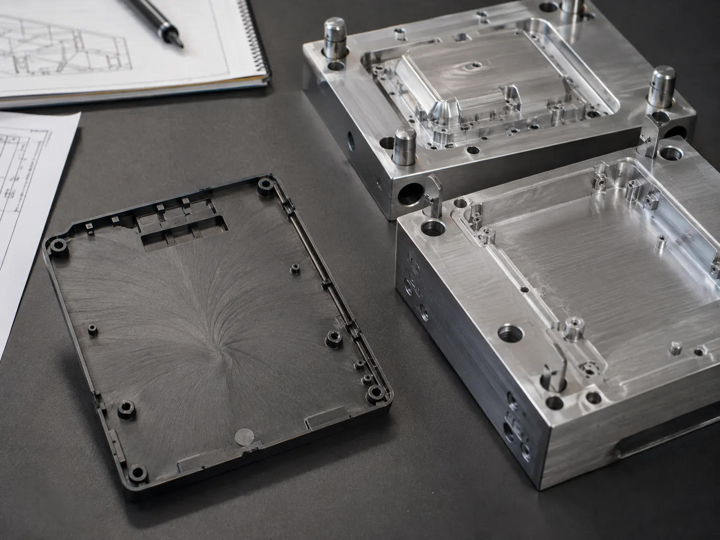
An unsuitable gate location can create excessive flow length, air traps, weak weld lines, uneven packing, sink marks, warpage, and cosmetic gate marks. The best location depends on part geometry, resin, wall thickness, cosmetic requirements, and functional loading. Gate design should therefore be reviewed together with the overall mold structure. Learn more about HPDI's prototype injection molding process.
Edge Gates
Edge gates are common in prototype and low-volume molds because they are relatively simple to machine and modify. They introduce resin through the edge of the component and are suitable for many housings and structural parts. Advantages include simple tool construction, easy gate-size modification, reliable filling, and compatibility with many thermoplastics. The main disadvantage is the visible gate vestige after removal.
Tab Gates
A tab gate introduces resin through a small sacrificial tab connected to the component. The tab can reduce localized stress where the melt enters the cavity and may improve flow for certain flat components. Tab gates can be useful when the part is sensitive to jetting, stress around the gate must be reduced, or a controlled entry profile is desirable. The tab requires a secondary trimming operation. Learn more about HPDI's manufacturing facilities.
Fan Gates
Fan gates spread molten plastic over a wider area. This can be useful for broad, thin-wall components because the wider flow front reduces localized flow velocity. Typical applications include flat housings, panels, covers, and wide structural parts. Fan gates can help reduce some flow-related distortion, but they also create a wider gate vestige that must be removed.
Pin Gates and Tooling Complexity
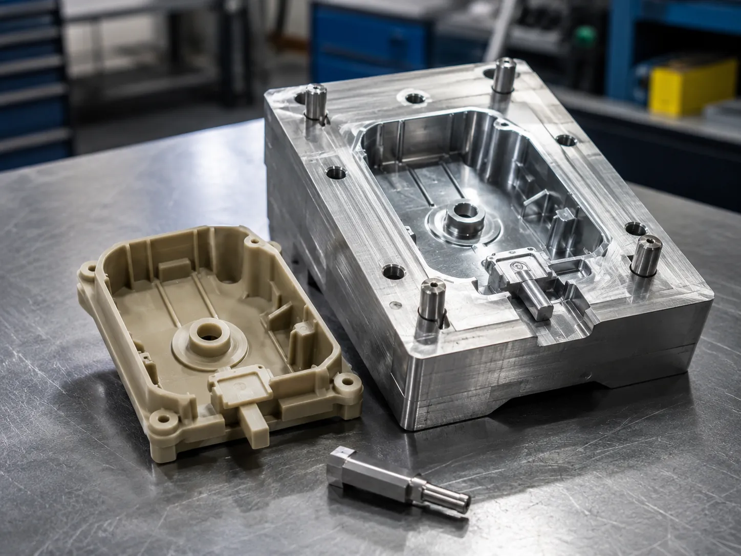
Pin gates provide a smaller, more concentrated injection point and can support automatic gate separation in certain tool designs. However, they generally require more complex runner arrangements than simple edge gates. For a simplified prototype mold, engineers should determine whether the additional tooling complexity produces enough validation value to justify it. Learn more about HPDI's case studies.
Gate Size Is Critical
A gate that is too small may freeze before adequate packing pressure reaches the cavity, causing sink marks, voids, low part weight, or dimensional variation. A gate that is unnecessarily large may increase gate marks and trimming requirements. Prototype tooling allows engineers to test and adjust gate dimensions before the production mold design is finalized.
Weld Line Position
When two resin flow fronts meet, a weld line can form. Its position is especially important on structural components. A weld line should ideally not be located in areas subject to high mechanical stress, sealing loads, or repeated flexing. Changing gate position can shift weld lines to less critical areas. Learn more about HPDI's FAQ.
Glass-Fiber Orientation
For glass-filled materials, resin-flow direction influences fiber orientation. The molded part may show different shrinkage and mechanical behavior parallel and perpendicular to flow. Gate design can therefore affect strength, warpage, dimensional stability, and surface appearance. Reinforced materials should be evaluated early during prototype molding.
Use Mold Flow as a Guide, Not a Substitute for Testing
Flow simulation can help compare gate locations, pressure, weld-line position, and filling balance before metal is cut. However, simulation still relies on material data and assumptions. Prototype molding provides the physical evidence needed to confirm whether the predicted gate strategy works with the real tool, resin, machine, and part geometry. The strongest development process uses simulation to narrow the options and the prototype mold to validate the final decision. Learn more about HPDI's submit part drawings.
Consider Gate Vestige during Product Design
Gate removal is not only a tooling issue. The product designer should decide where a visible vestige is acceptable, whether trimming can be automated, and whether the remaining mark can interfere with assembly or sealing. A gate hidden inside a housing may be acceptable even if it is visually rough, while a cosmetic exterior panel may require a different gate strategy. Identifying the preferred gate zone early can prevent late compromises in tool design.
Record Gate Changes after Each Trial
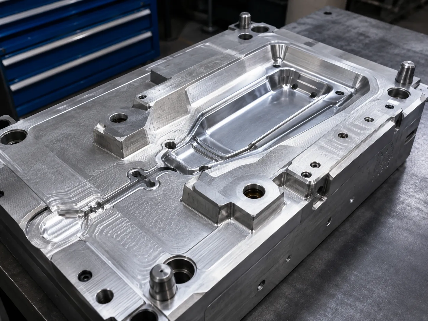
If gate size or location changes between T1 and T2, document the modification and compare part weight, filling pressure, warpage, weld lines, and critical dimensions. Without controlled records, a team may know that the second trial is better but not understand why. This information becomes especially valuable when the production mold uses a different runner layout or cavity count because the prototype results provide a proven starting point for the new design.
Gate Strategy for Future Multi-Cavity Production
A prototype tool may use a simple gate that is not identical to the future production runner system. Even so, the prototype can validate the preferred filling direction, acceptable gate zone, weld-line risk, and packing response. When a multi-cavity production mold is later designed, those findings can guide runner balance and cavity orientation. The goal is to transfer the proven flow behavior while adapting the gate and runner hardware to the higher-output production system.
Conclusion
Gate design for aluminum prototype injection molds affects far more than where plastic enters the cavity. It influences flow length, pressure, weld lines, fiber orientation, shrinkage, warpage, strength, and cosmetic quality. Prototype tooling provides a valuable opportunity to validate these factors while changes remain relatively easy to implement.