

Cooling and Warpage Control in Aluminum Injection Molds
Why Warpage Appears during Prototype Molding
Warpage is one of the most common problems discovered during prototype injection molding. A part may look perfectly flat in CAD but distort after molding because different regions cool and shrink at different rates. In aluminum injection molds, cooling behavior deserves particular attention because the thermal characteristics of aluminum differ from conventional production tool steels.
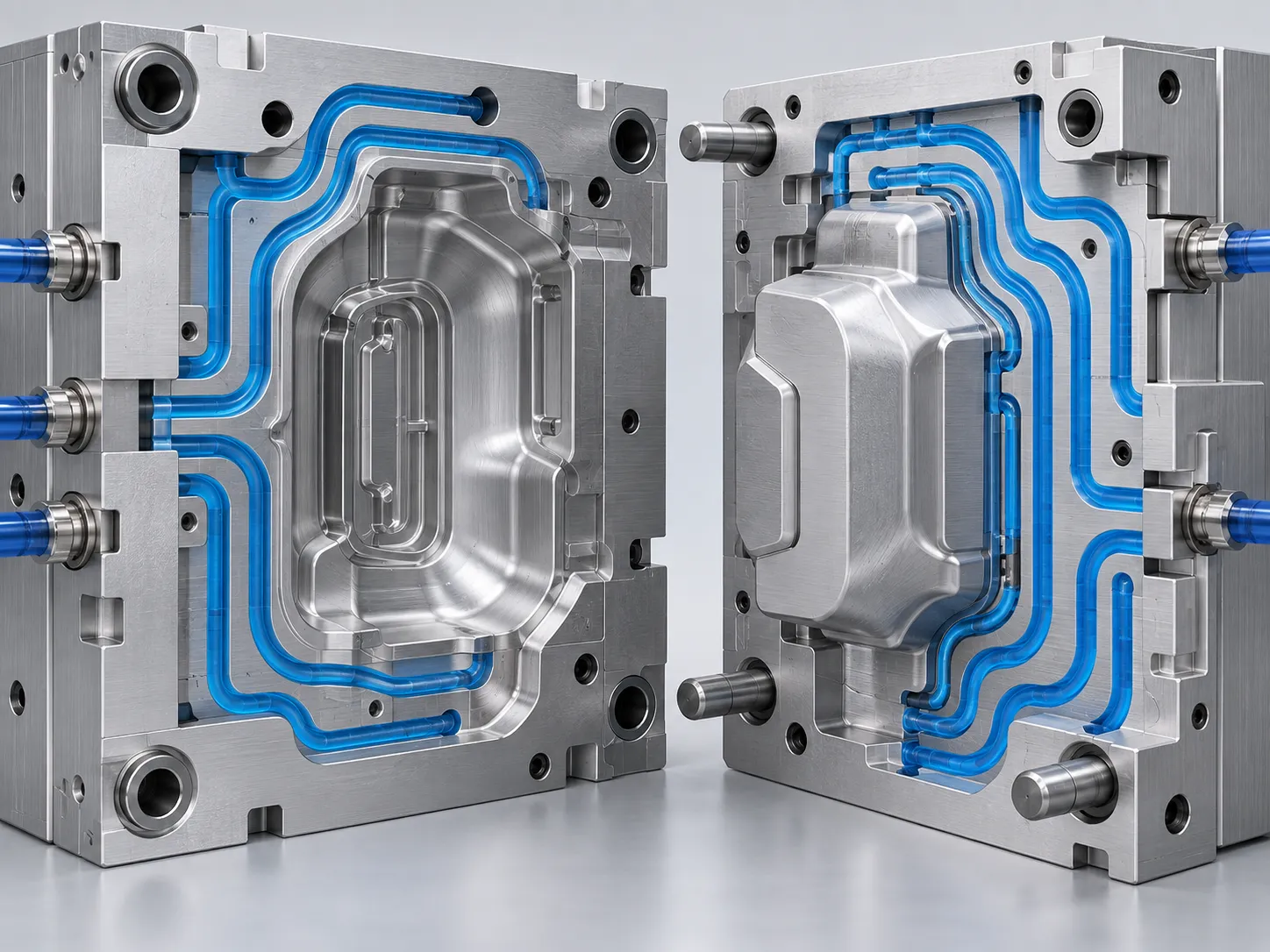
Why Injection-Molded Parts Warp
Warpage occurs when shrinkage is not balanced throughout the component. Contributing factors include uneven wall thickness, asymmetrical ribs, uneven cooling, gate location, fiber orientation, packing pressure, mold temperature, and part geometry. A warped prototype provides valuable engineering information because the same risk may continue into production unless the underlying cause is corrected. Learn more about HPDI's prototype injection molding.
Aluminum Conducts Heat Efficiently
Aluminum generally transfers heat more efficiently than many conventional mold steels. This can be advantageous because heat can move away from the cavity surface rapidly. However, efficient heat transfer does not automatically guarantee uniform cooling. A mold with poorly positioned cooling channels can still produce temperature differences across the cavity.
Uniform Wall Thickness Comes First
Cooling cannot fully compensate for poor part geometry. A thick plastic section stores more heat and cools more slowly than a thin section. When one region remains hot while neighboring areas have already solidified, differential shrinkage can pull the component out of shape. Engineers should therefore try to maintain relatively uniform wall thickness and use ribs rather than large solid sections where possible. Learn more about HPDI's facilities.
Ribs Can Create Hidden Distortion
Ribs increase stiffness but can also create localized thickness. Several large ribs positioned on one side of a flat housing may create an unbalanced structure. During cooling, the ribbed side can shrink differently from the opposite surface, causing the housing to curve. Prototype molded parts allow the product team to measure this effect before production tooling is completed.
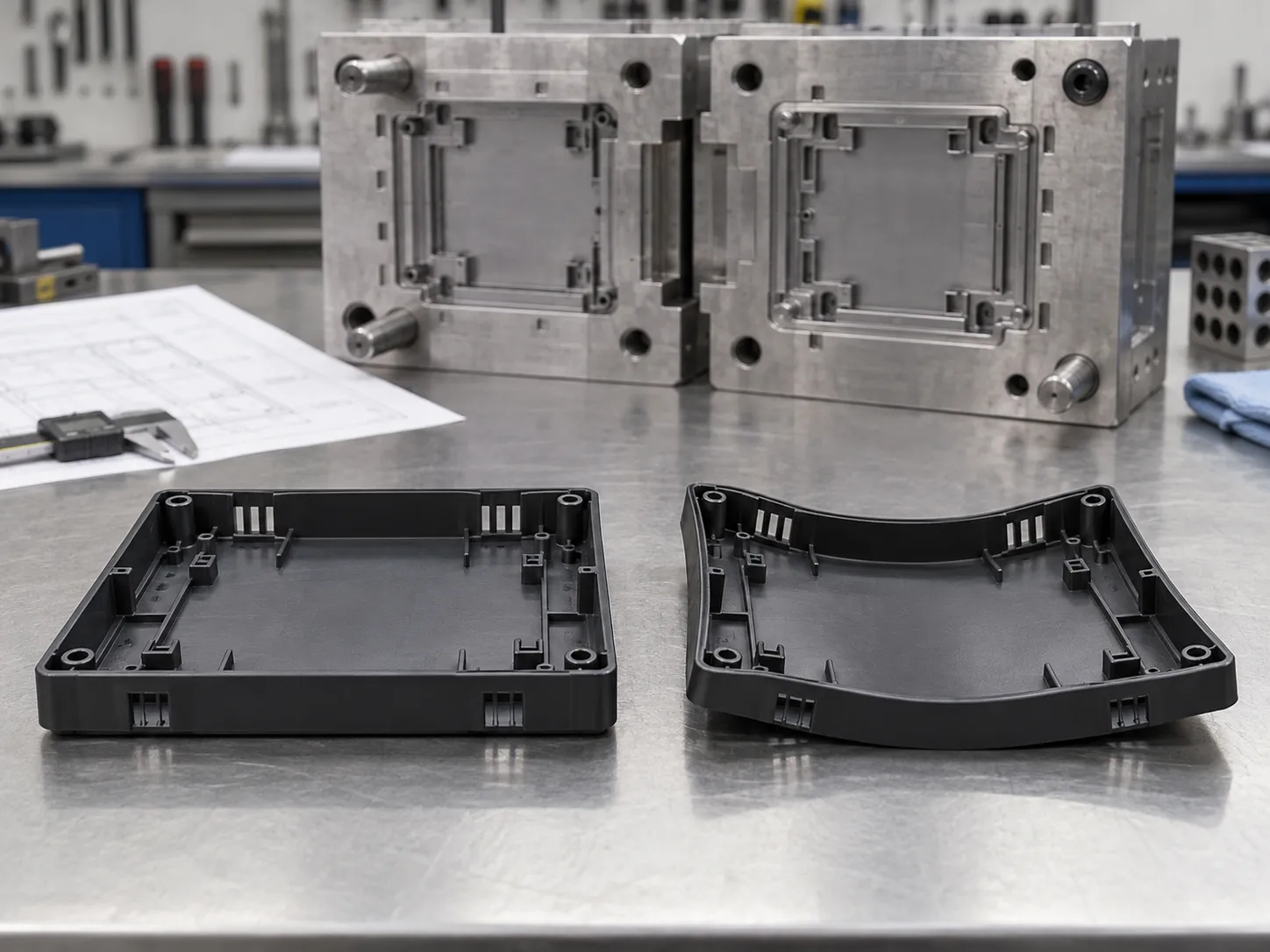
Mold Temperature Must Be Controlled
A mold that is too cold can create poor surface replication, difficult filling, and high internal stress. A mold that is too hot may increase cooling time and create different shrinkage behavior. The correct temperature depends on the thermoplastic, and engineering materials such as PC, PA, POM, PPS, or PEEK may require very different conditions. Learn more about HPDI's case studies.
Packing Pressure Influences Shrinkage
After the cavity is initially filled, packing pressure compensates for material shrinkage while the gate remains open. Insufficient packing can contribute to sink marks, low density, and dimensional variation. Excessive packing can create high molded-in stress, difficult ejection, and unwanted dimensional changes. Prototype molding helps establish a stable processing window.
Gate Location Can Affect Warpage
Gate position determines resin-flow direction and packing distribution. If one section of the cavity is difficult to pack, it may shrink more than another. For glass-filled materials, gate position also affects fiber orientation, which can create anisotropic shrinkage. Gate design and warpage control should therefore be evaluated together. Learn more about HPDI's FAQ.
Measure the Molded Parts
Warpage should be measured rather than estimated visually. Inspection may include flatness measurement, CMM inspection, fixture checks, gap measurement, and assembly testing. Objective measurement helps separate process variation from genuine design or tooling problems.
Distinguish Mold Cooling from Part Cooling
Cooling time on the molding machine is only one part of thermal control. Some parts continue to change after ejection as internal temperature equalizes and residual stress relaxes. Engineering teams should define when dimensions are measured and whether the parts require conditioning before inspection. Comparing a part measured immediately after molding with one measured after 24 hours can create false conclusions about mold accuracy or process stability. Learn more about HPDI's engineering review.
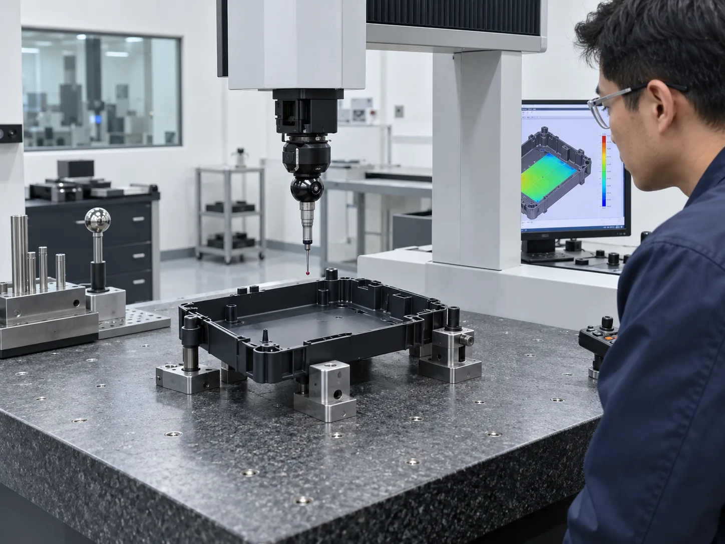
Use Temperature Data during Troubleshooting
When warpage is inconsistent, measure rather than guess. Surface temperature checks, mold-temperature records, cavity pressure where available, part weight, and dimensional trends can reveal whether the problem comes from thermal imbalance or another cause. Even simple temperature measurements at corresponding areas of the core and cavity can show whether one region is cooling much faster than another. This makes modifications to cooling or cycle time more targeted.
Validate the Corrective Action
After a warpage correction, repeat the same inspection method used for the original samples. A process change that improves one dimension may worsen another, and a geometric change can affect both filling and assembly. Use a small controlled molding study to confirm that the improvement remains stable across multiple cycles. The goal is not to produce one flat part but to establish a process window that consistently produces parts within the functional requirement.
Account for Post-Mold Conditioning
Some engineering plastics continue to change dimensions after molding because of moisture absorption, crystallization, or stress relaxation. A part that appears flat immediately after ejection may move after conditioning, while another may stabilize over time. The inspection plan should therefore define storage conditions and measurement timing. For moisture-sensitive nylon or other conditioning-dependent materials, this distinction is essential when deciding whether a dimensional change comes from the mold, the process, or normal material behavior.
Compare Warpage with Functional Requirements
Not every visible distortion is functionally important. A cosmetic cover may tolerate slight curvature, while a sealing surface or bearing interface may require much tighter flatness. The validation team should define acceptable warpage using assembly and function, not appearance alone. This prevents unnecessary tool changes and focuses cooling improvements on dimensions that actually affect product performance.
Conclusion
Cooling and warpage control in aluminum injection molds require a combination of good part design, suitable mold construction, correct material selection, and stable processing. Aluminum's thermal characteristics can support efficient prototype molding, but uniform heat removal remains essential. Prototype tooling is valuable because it exposes manufacturing risks while they are still inexpensive to correct.