

Prototype Injection Mold Design for Easier Engineering Changes
Prototype tooling has a different job from a production mold. A production tool is optimized after the product, material and process are stable. A prototype tool is often built while some of those decisions are still being validated. For that reason, good prototype injection mold design should make likely engineering changes easier rather than treating every cavity detail as permanent.
This does not mean building a disposable or inaccurate tool. It means identifying which areas are stable, which features may change after T1 and where the mold should preserve flexibility. HPDI’s prototype injection molding service uses simplified steel, aluminum and bridge tooling according to project stage and expected use.
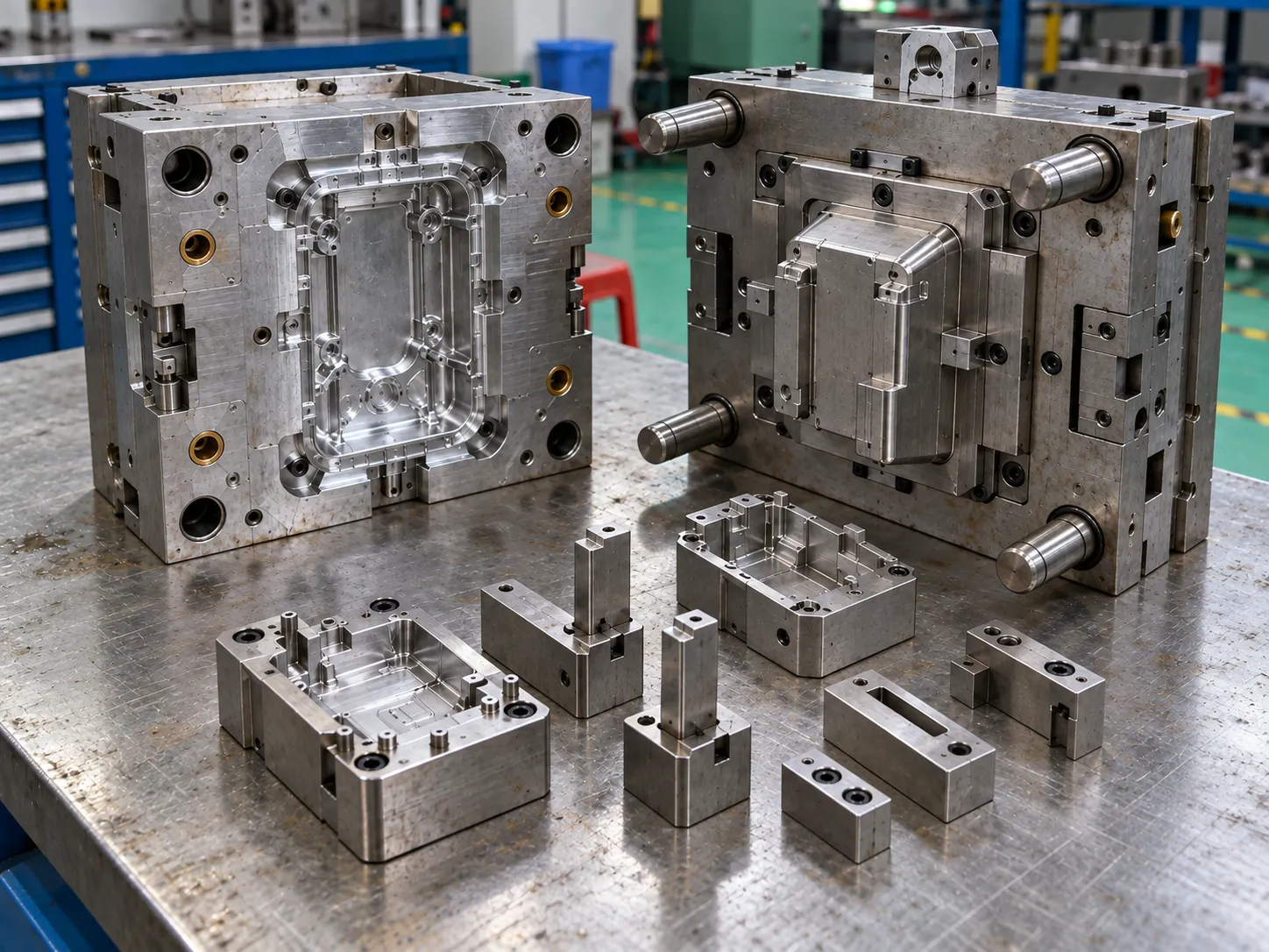
Which features are most likely to change after T1?
Functional interfaces deserve the most attention. Snap-fits may need different engagement. Screw bosses may need diameter or support changes. Connector openings can shift after assembly testing. Sealing features may need local adjustment. Ribs can be modified to improve stiffness or reduce sink. Gate regions may also change if filling or weld-line behavior is not acceptable.
If these features are identified before machining, the mold designer can decide whether they belong in separate inserts or should be left in a steel-safe condition.
What does “steel-safe” mean in prototype tooling?
Steel-safe design leaves the mold in a condition where a likely dimensional change can be made by removing tool material rather than adding it. The exact direction depends on the feature. For example, a shutoff or cavity detail can be intentionally biased so that later machining moves the molded dimension toward the final target.
This principle is useful because removing metal is usually more controlled than welding and re-machining a finished cavity. Steel-safe planning requires agreement between the product engineer and mold designer about which dimensions have genuine uncertainty.
When are replaceable inserts worth using?
Replaceable inserts are useful when a local feature has a high probability of revision or when a wear-sensitive area may need a different material. Typical candidates include snap hooks, connector details, logos, local ribs, sealing geometry, gate areas and complex shutoffs. Instead of reworking the full cavity, the mold maker can modify or remake only the insert.
This approach can also separate aluminum and steel within the same prototype tool. A main aluminum cavity may use steel inserts at gates or sliding interfaces when wear resistance is more important locally.
How should the mold design support root-cause testing?
A prototype tool should make it practical to test one hypothesis at a time. If a gate insert can be changed, engineers can compare filling behavior. If a local rib insert can be re-machined, they can measure the effect on sink or stiffness. If the ejection system is accessible, they can diagnose drag or deformation without rebuilding the mold.
The existing DFM checklist helps identify these likely risk areas before tool design. Good DFM and good prototype-tool design are closely linked because both focus on preventing expensive late-stage changes.
How do aluminum and simplified steel differ for modification?
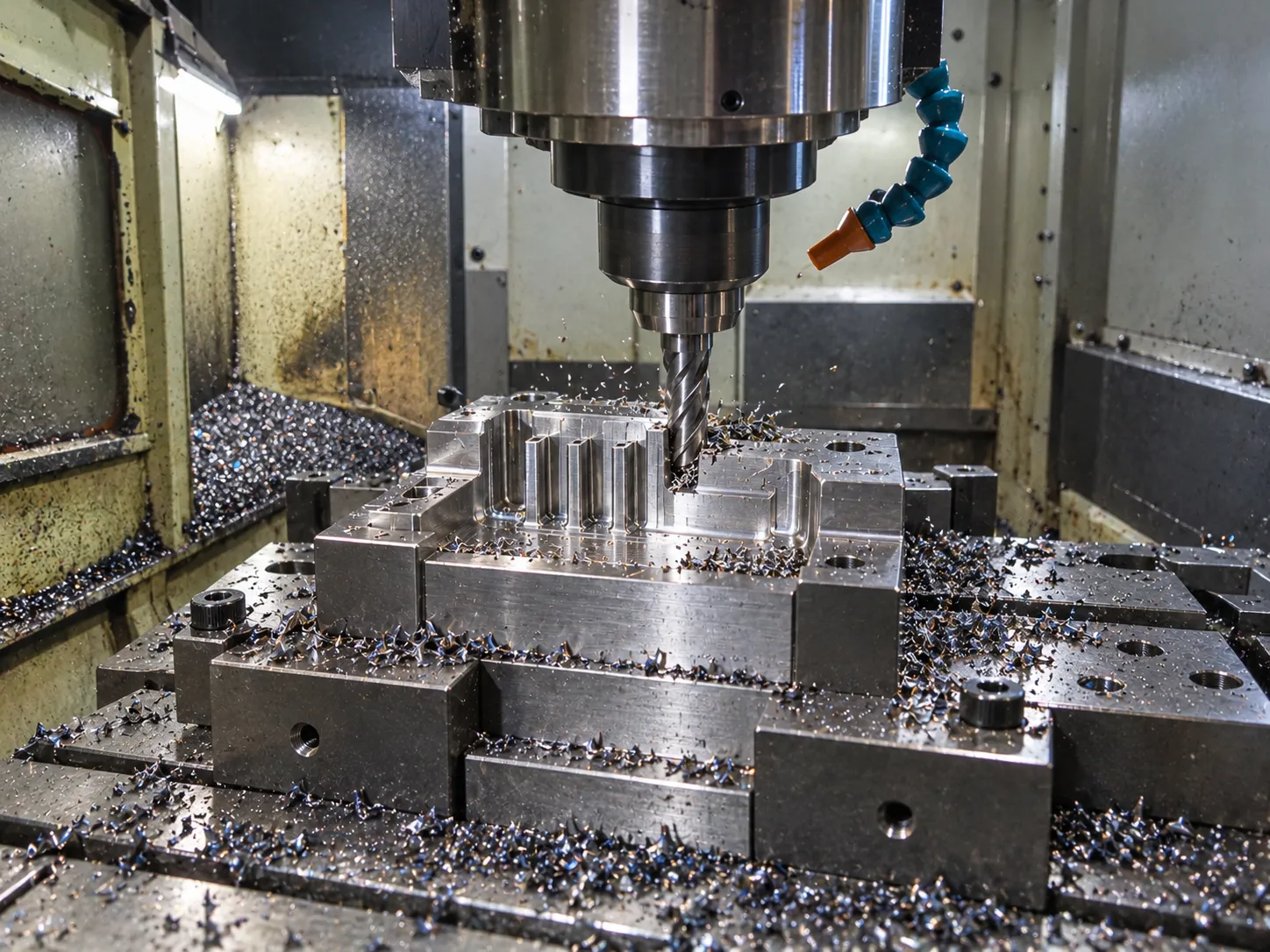
Aluminum is attractive when machining speed and repeated local changes are important. Simplified steel can provide greater wear resistance where abrasive resins, repeated trials or demanding shutoffs are expected. The right choice depends on the resin, geometry, expected validation cycle and planned quantity rather than on a general rule that one material is always faster or cheaper.
HPDI’s facilities include CNC and EDM machining, mold manufacturing, molding and inspection, allowing revised inserts or cavity details to be returned quickly to the trial loop.
Change-control checklist for prototype molds
Before approving a mold change, document:
- The problem observed in the molded part or assembly.
- The measured feature linked to that problem.
- Whether the root cause is design, tool or process.
- The CAD and drawing revision being changed.
- The mold component or insert affected.
- The expected result of the change.
- The acceptance check for the next trial.
This prevents multiple undocumented modifications from creating confusion about which change improved or worsened the part.
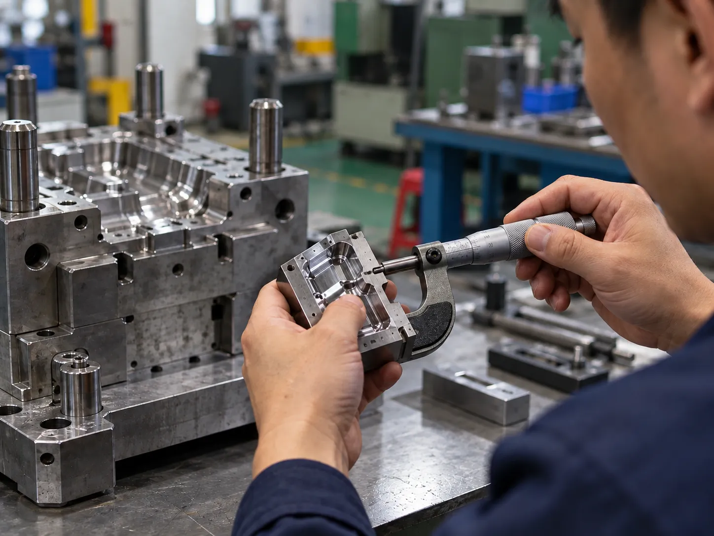
How does ejection strategy affect future changes?
Ejection should also be designed with prototype flexibility in mind. If ejector pins occupy likely change areas, a later rib or boss modification can become unnecessarily difficult. Deep ribs, textured cores and thin walls may also need a more distributed ejection strategy so that the first trials do not confuse ejection deformation with true part warpage.
Before machining, review the likely design-change zones together with the ejector layout. This small planning step can preserve space for new inserts, local machining or revised geometry without rebuilding large sections of the tool.
Conclusion
Prototype injection mold design should preserve engineering options. Steel-safe dimensions, replaceable inserts, accessible gates and a deliberate change-control process make post-T1 correction faster and more informative. The best prototype tool is not the one that never changes; it is the one that helps the team learn efficiently and transfer validated decisions to production.
For guidance on likely tooling changes, review HPDI’s FAQ or send the current CAD and drawing for an engineering review.