

Prototype Injection Mold Tolerances: Drawing and Inspection Guide
Tolerances written for a machined metal component should not automatically be copied onto an injection-molded plastic drawing. Resin shrinkage, wall thickness, fiber orientation, cooling and post-molding conditioning can change part dimensions even when the tool was manufactured accurately. For a prototype mold, the goal is to control dimensions that influence function while learning how the material and molding process behave. This guide explains which characteristics deserve tight control, what to include on drawings and how to agree an inspection plan before machining simplified steel or aluminum tooling.
What Is a Realistic Prototype Injection Mold Tolerance?
There is no responsible single tolerance that fits every part. A small rigid feature, a long flat housing and a glass-filled component may exhibit different dimensional behavior. The correct specification starts with the required fit and use conditions, then checks whether the chosen resin, geometry, mold design and process can achieve it. ISO 20457:2026 provides a plastics-specific framework for dimensional and geometrical tolerances and related acceptance conditions; it does not replace project-specific engineering agreement.
Classify Dimensions by Function Before Assigning Limits
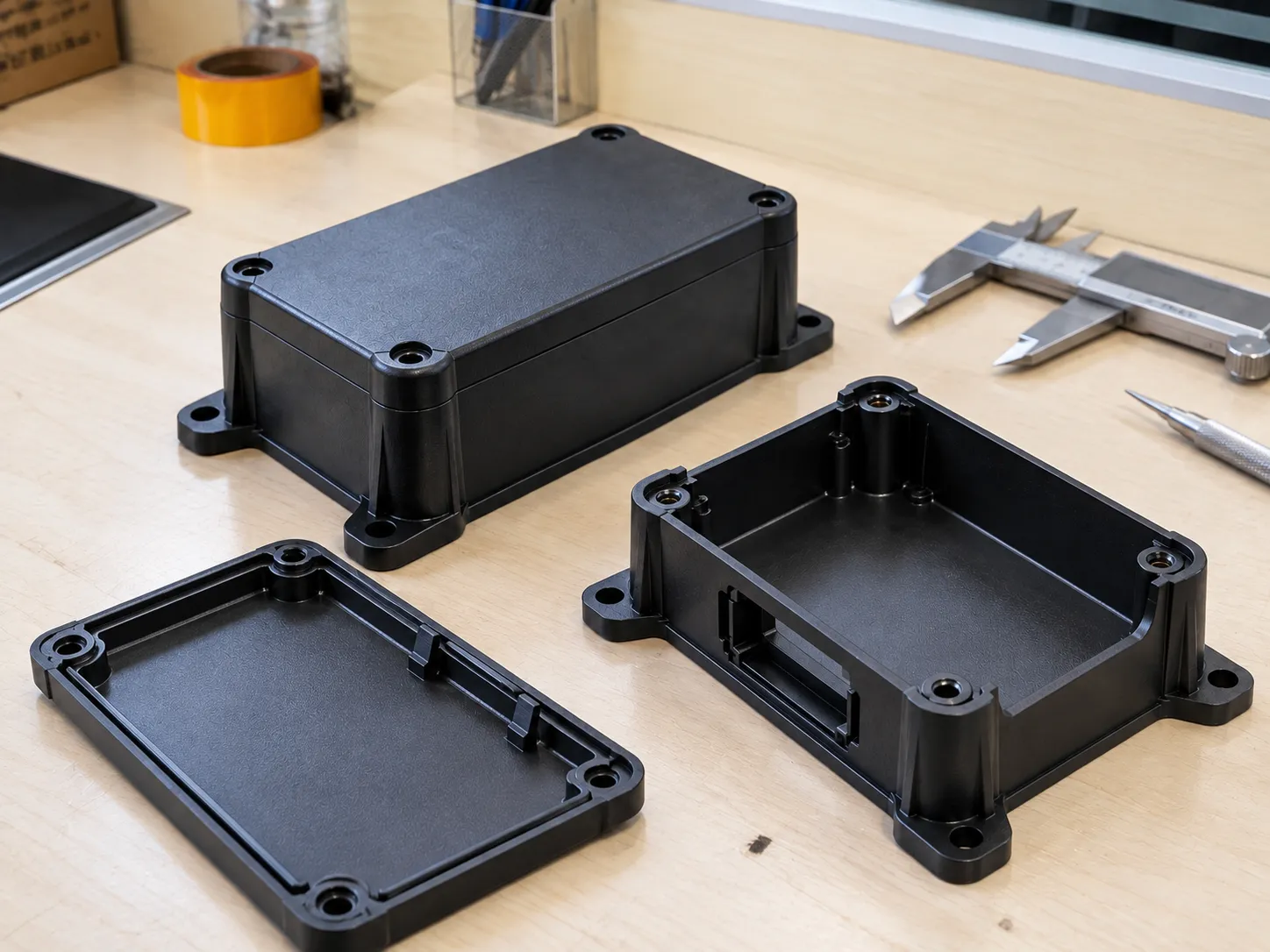
Mark the characteristics that affect sealing, connector alignment, fastening, movement, safety or assembly. These critical-to-function dimensions need explicit limits and an agreed measurement method. Other features may only need a reasonable general tolerance or a reference dimension. Treating every decorative radius or nonfunctional surface as precision-critical can increase tooling effort without improving product performance. The distinction should be visible in the controlled 2D drawing sent for prototype mold design and molding review.
| Feature class | Typical example | Recommended drawing or inspection approach |
|---|---|---|
| Functional interface | Snap-fit clearance or connector location | Individual tolerance and defined datum |
| Sealing / mounting | Gasket face or screw boss spacing | Function-driven profile or position control |
| Cosmetic geometry | Non-mating external contour | Appearance criteria or appropriate general tolerance |
| Reference geometry | Informational envelope dimension | Clearly mark reference-only status |
Choose Datums and Measure the Part Consistently
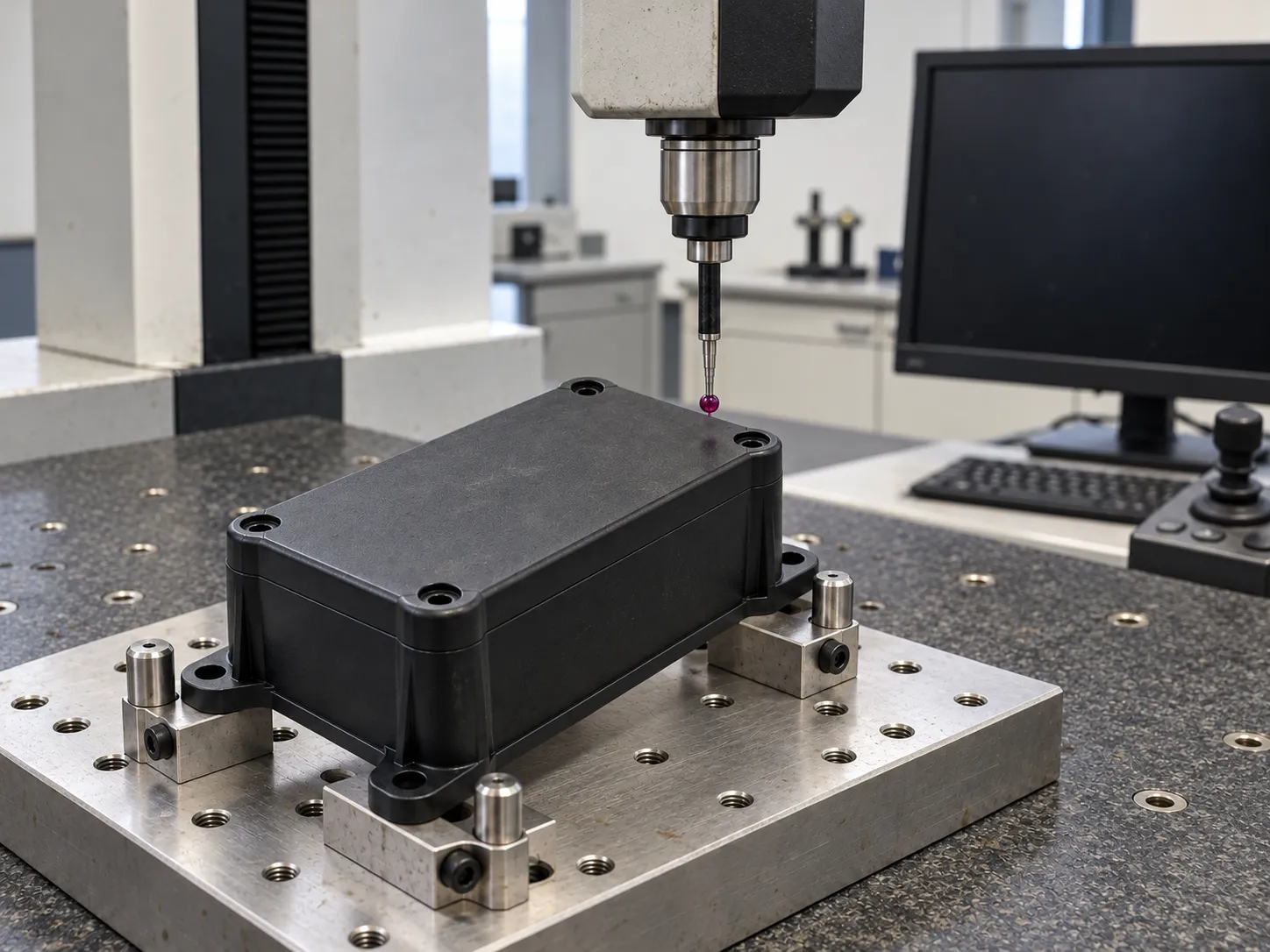
A dimension is useful only if it can be measured repeatably. Specify primary locating surfaces or datums that reflect how the product is assembled, and distinguish free-state measurement from fixtured measurement where appropriate. A thin housing measured while clamped may appear compliant but return to a different shape after release. Define the inspection fixture, relevant environment and any required post-molding conditioning before acceptance testing. Where different instruments are used, agree how results will be compared rather than assuming that every measuring method gives the same answer.
Account for Shrinkage, Warpage and Resin Conditioning
Plastic molding variation comes from both material behavior and process conditions. Nonuniform walls, asymmetric ribs or an unsuitable gate can create differential shrinkage and warpage. Filled resins can show direction-dependent behavior because reinforcement follows melt flow. Some polymers also change dimensions after moisture exposure or thermal conditioning. Identify the exact grade, filler level and application environment before setting limits. The engineering team should review part design and molding feasibility using the available machining and measurement equipment together with material guidance.
Does an Aluminum Prototype Mold Require Looser Tolerances?
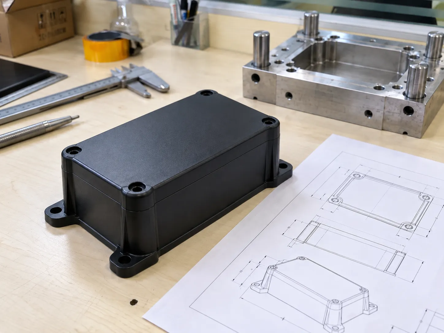
Not automatically. Aluminum can produce useful engineering prototypes when the tool is correctly designed and maintained. However, mold-material stiffness, thermal expansion, wear-sensitive shutoffs, cavity layout and expected number of cycles must be considered. Simplified steel tooling may be preferable for abrasive resins or extended trials. A complex part with unrealistic dimensions will not become accurate simply because the mold is steel. Select the tool material from the part requirements, resin and validation program rather than treating either material as a universal precision guarantee.
Use T1 Inspection to Separate Part and Process Problems
A T1 sample review should record part revision, resin grade, molding conditions, measurement method and the actual results for marked characteristics. Inspect multiple relevant samples when the objective includes variation, not merely whether one part happens to fit. If a dimension misses its requirement, investigate whether the cause is cavity size, shrinkage assumption, gate position, cooling imbalance, ejection distortion or conditioning. Record the corrective action and reassess after the next trial. The HPDI quotation and tooling FAQ identifies the drawing and mold information that helps start this review.
A Pre-Tooling Tolerance Checklist
Before cutting metal, confirm that the drawing identifies critical features, datums, acceptance criteria, resin, required appearance, expected quantity and inspection conditions. Ask whether any limit is tighter than the product function actually demands. Clarify dimensions that are difficult to reach with a probe, features measured across a parting line and surfaces likely to deform under contact. If the purpose is exploratory testing, distinguish target dimensions from final production acceptance requirements. Document who approves revisions when the first molded parts reveal a needed design change.
Conclusion: Specify Function First, Then Verify Moldability
Effective prototype injection mold tolerances describe how the plastic part must work, not just how precisely the mold can be machined. Prioritize functional interfaces, use consistent datum-based measurement and review resin-dependent behavior before tooling release. For a simplified steel or aluminum mold, an early tolerance discussion can prevent unnecessary modifications and make T1 inspection far more useful. Share your CAD model and drawing with HPDI to review critical dimensions and the intended prototype validation plan.