

Prototype Molding for Glass-Filled Engineering Plastics
Glass-filled engineering plastics are widely selected when a plastic component needs more stiffness, heat resistance or structural performance than an unfilled resin can provide. The reinforcement also changes how the material flows, shrinks and interacts with the mold. As a result, a part that looks straightforward in CAD may show directional warpage, visible fiber patterns or unexpected dimensional behavior after molding.
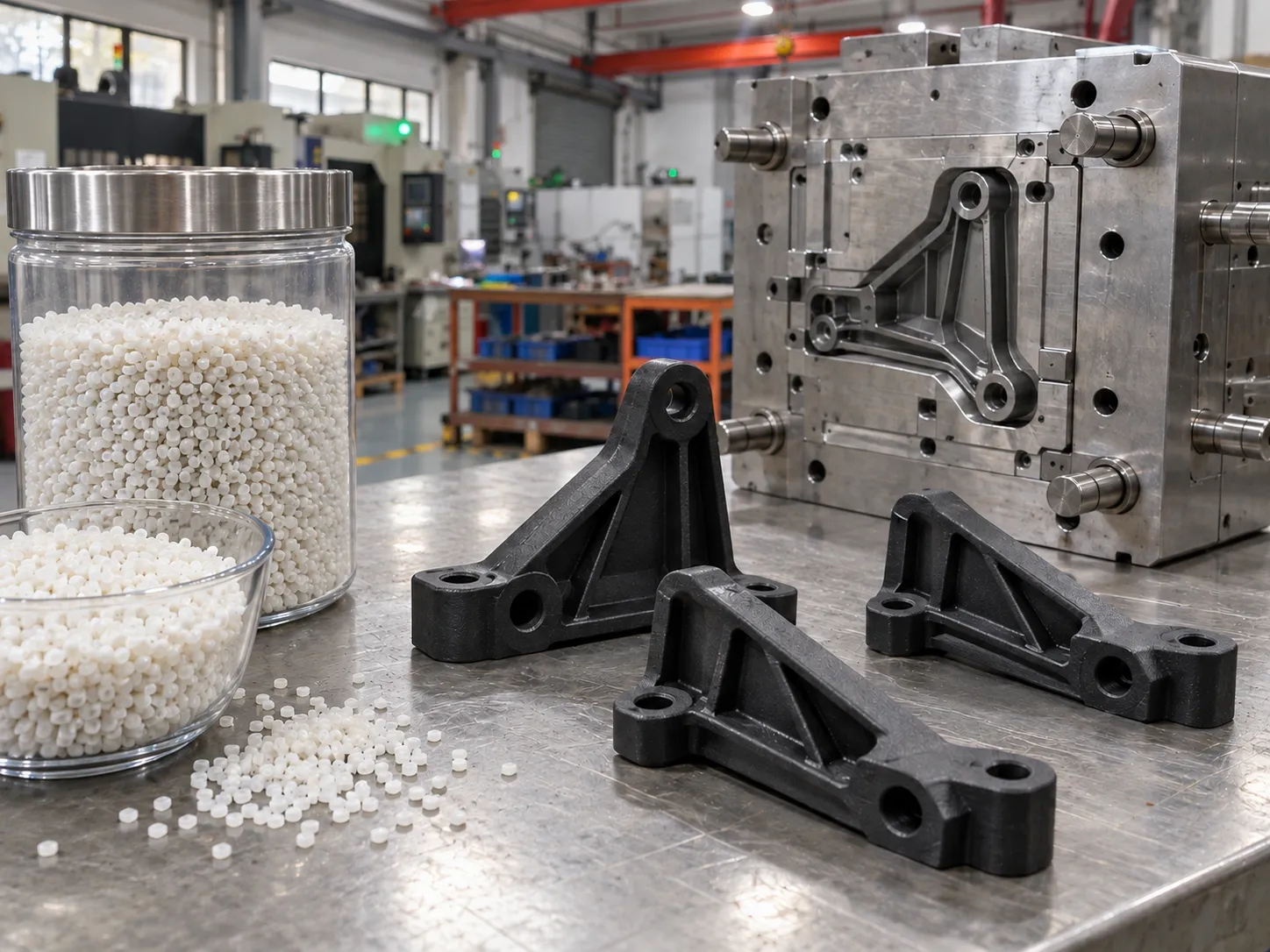
Prototype molding for engineering plastics allows these risks to be tested in the real component geometry. HPDI’s prototype injection molding service can use simplified steel, aluminum or hybrid tooling depending on the resin, part design and validation objective.
Why are glass-filled plastics different to mold?
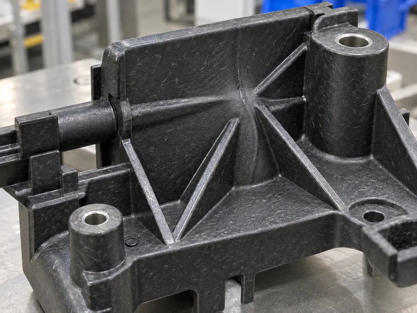
The fibers tend to align with the direction of flow as the melt fills the cavity. This can improve stiffness in one direction while also creating directional shrinkage. Areas fed from different directions may meet at a weld line with a different local fiber structure. Thin ribs or long flow paths can further amplify the effect.
The mold and process therefore influence final part behavior more strongly than a simple material datasheet suggests. That is why molded prototypes are important when the part has critical flatness, load-bearing ribs or tightly controlled assembly interfaces.
How should gate position be evaluated?
Gate position controls the initial flow direction and can influence fiber orientation throughout the component. For a structural bracket, the team should consider whether the main flow direction supports or conflicts with the primary load path. For a flat housing, the team should also watch whether the flow pattern creates asymmetric shrinkage and warpage.
Prototype tooling gives engineers a practical opportunity to confirm the gate strategy before a production tool is finalized. The existing injection molded prototype process guide provides broader context on tooling, molding and validation.
Why can reinforced resin increase mold wear?
Glass fibers and mineral fillers can be abrasive, particularly at high-velocity regions such as gates, runners, shutoffs and sliding interfaces. Tool material should therefore be selected with the actual resin in mind. Aluminum may still be useful for some development programs, but local steel inserts or simplified steel tooling may be more appropriate where wear is concentrated.
This is a good example of why “aluminum versus steel” should not be decided before the resin and part geometry are understood.
What material preparation needs attention?
Many engineering plastics are sensitive to moisture or thermal history. Material preparation should follow the resin supplier’s processing guidance, and the prototype trial should record how the material was conditioned before molding. Otherwise, the team may mistake a material-preparation problem for a design or tool problem.
When a defect appears, engineers should confirm material condition before changing the mold. This keeps the validation process evidence-based and prevents unnecessary tooling corrections.
What should be measured on the molded parts?
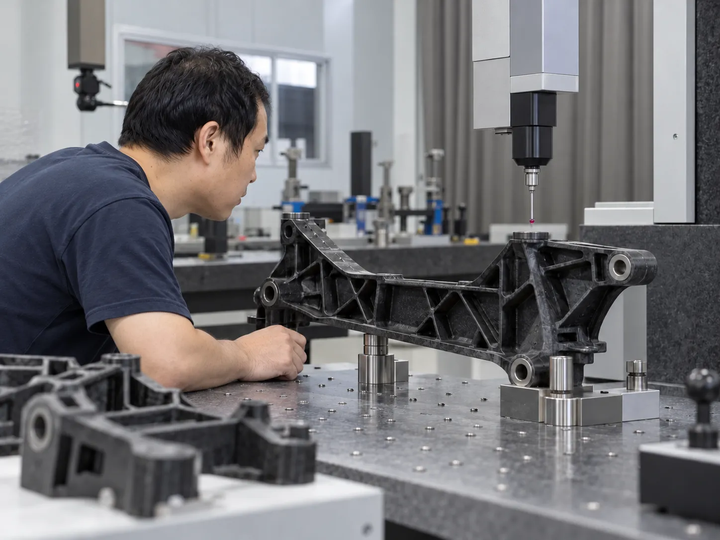
Important checks include flatness, critical hole spacing, boss position, snap-fit behavior, assembly force and any dimension that could be influenced by directional shrinkage. Visual inspection may also reveal fiber read-through, weld lines or flow marks that matter on exposed surfaces.
HPDI’s facilities include dimensional inspection resources that can support comparison between T1 parts and later revisions. For warpage-specific planning, the related temperature control and warpage guide is also relevant.
How should results influence the production mold?
The prototype program should record the final gate concept, known warpage direction, successful process condition, critical dimensional offsets and any local tool wear observed during trials. If the production mold will run larger quantities, these findings can guide steel selection, gate inserts, cooling and cavity compensation.
The objective is not to prove that the prototype tool and production tool are identical. It is to use the prototype tool to expose material behavior early enough that the production design can respond to it.
How should reinforced parts be conditioned and assembled?
The measured behavior of a reinforced molded part can continue to change after ejection, especially when the resin is sensitive to moisture or temperature. The validation plan should therefore define when dimensions are measured and how samples are conditioned before functional testing. Comparing one freshly molded sample with another part measured after different storage conditions can create misleading conclusions.
Assembly testing should use the real mating components whenever possible. Pay close attention to hole spacing, boss alignment, snap engagement and flatness across long interfaces. These checks connect fiber orientation and shrinkage to actual product performance instead of treating the material study as a separate laboratory exercise.
Conclusion
Glass-filled engineering plastics can deliver strong structural performance, but they also make flow orientation, shrinkage, moisture control and tool wear more important. Prototype injection molding gives engineers a practical way to evaluate these effects in the final part geometry before committing to production tooling.
For a reinforced-plastic project, review HPDI’s FAQ or contact the engineering team with the exact resin grade, drawing and validation requirements.